
Distribution barrel overturning device

A technology for turning barrels and barrel walls is applied in the field of automation of weaving dye factories, which can solve the problems of reducing work efficiency, multi-manpower, consumption, etc., and achieve the effects of improving controllability, improving flexibility, and improving automation and work efficiency.

Pending Publication Date: 2019-08-13
杭州盛格信息技术有限公司
View PDF0 Cites 0 Cited by
  • Summary
  • Abstract
  • Description
  • Claims
  • Application Information

AI Technical Summary

Problems solved by technology

[0003] At present, various manufacturers use manual operation for the steps of pouring small barrels of dyes into large barrels of dyes, which requires a lot of manpower, especially in large factories, the use of manual mixing of fuels will greatly reduce work efficiency

Method used


Image

  • Distribution barrel overturning device
  • Distribution barrel overturning device
  • Distribution barrel overturning device

Examples


Embodiment 1

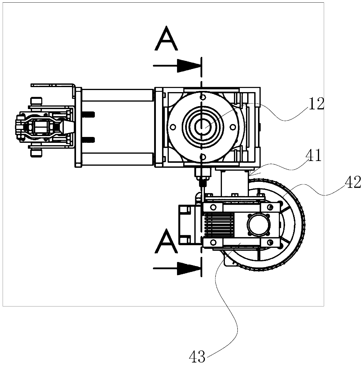
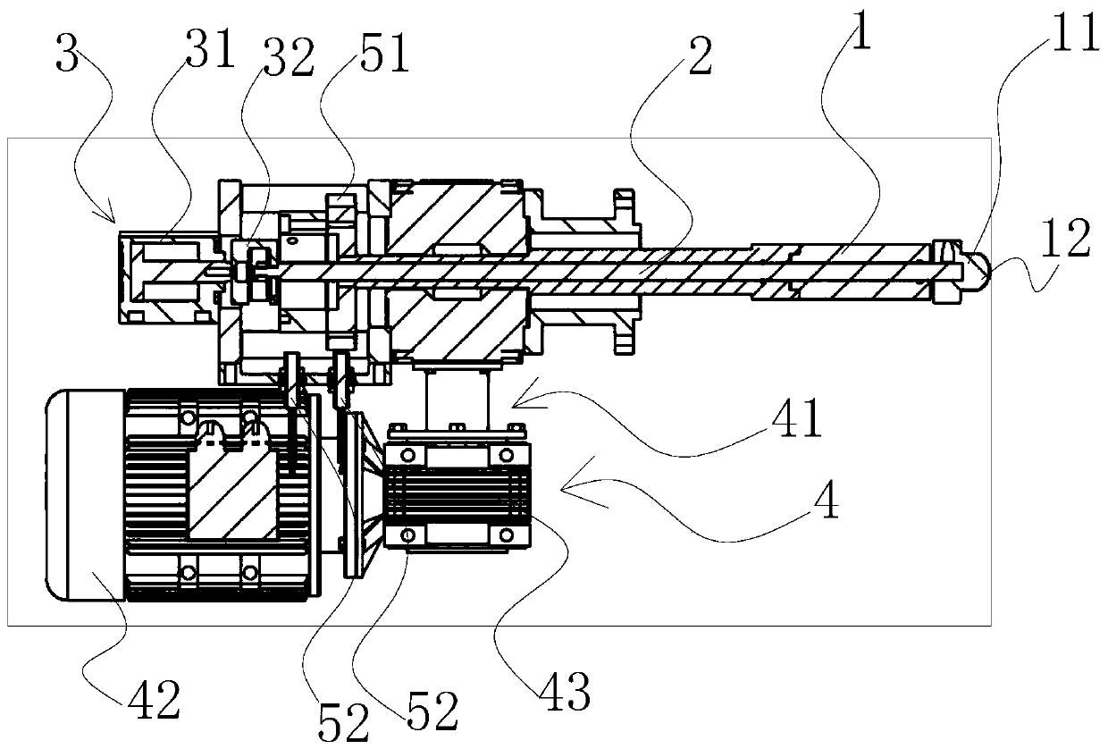
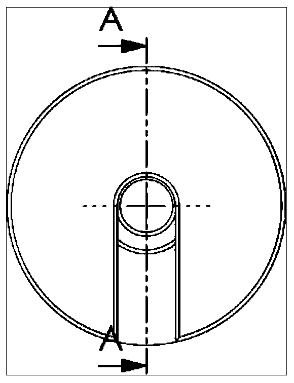
[0028] Such as figure 1 and figure 2 As shown, the present embodiment has opened a kind of delivery bucket turning device, comprises the first bucket turning structure, and the first bucket turning structure comprises a barrel pressure bar 1 with a keg wall contact portion 11 at one end, and the keg wall contact portion 11 is used In order to connect the outer wall of the keg, the end of the barrel pressing rod 1 away from the contact portion 11 of the keg wall has a turning bar 2, the turning bar 2 and the pressing bar 1 can be set as one body or can be a split structure and connected to each other. The end of the barrel rod 2 far away from the barrel pressing rod 1 is connected with a telescopic control mechanism 3 for the telescopic barrel turning lever 2 and a rotation control mechanism 4 for circumferentially rotating the barrel turning lever 2, and the telescopic control mechanism 3 and the rotation control mechanism 4 are both connected on the controller.

[0029] Sp...

Embodiment 2

[0039] This embodiment is similar to Embodiment 1, the difference is that the distribution bucket turning device of this embodiment also includes a second bucket turning structure opposite to the first bucket turning structure, and the second bucket turning structure is the same as the first bucket turning structure. The structure has the same structure, and the keg 6 is located between the first turning structure and the second turning structure. Of course, if Figure 8 As shown, the outer wall of the keg here has two opposite pressure grooves 61 .

[0040] When put into use, the keg 6 is placed in the middle of the first turning structure and the second turning structure. After the installation is completed, the bucket turning action can be started. Here, the opposite resistance force on both sides is mainly used to complete the bucket turning action on the keg 6 to ensure the stability of the keg 6, and here the pressing platform 12 is circumferentially outward and the press...


PUM


Abstract

The invention provides a distribution barrel overturning device which comprises a first barrel overturning structure. The first barrel overturning structure comprises a barrel pressing rod with a small barrel wall contact part at one end, the small barrel wall contact part is used for being connected with the outer side wall of a small barrel, a barrel overturning rod is arranged at the end, far away from the small barrel wall contact part, of the barrel pressing rod, the end, far away from the barrel pressing rod, of the barrel overturning rod is connected with a telescopic control mechanismfor stretching and retracting the barrel overturning rod and a rotary control mechanism for circumferentially rotating the barrel overturning rod, and the telescopic control mechanism and the rotary control mechanism are both connected with a controller. The small barrel is overturned through the barrel overturning device, and the automation degree and the working efficiency of a dye plant are improved.

Description

technical field [0001] The invention belongs to the technical field of automation of weaving and dyeing factories, and in particular relates to a bucket turning device for distribution. Background technique [0002] At present, the degree of automation of factories is getting higher and higher, and the dye factory used for dyeing cloth is no exception. The transmission and stirring of dyes are carried out by automatic means. In addition to the transmission and stirring of dyes, dyes also need to be mixed. The dyes are poured into the same vat, and then mixed automatically in the vat using means such as stirring rods. [0003] At present, various manufacturers use manual operation for the steps of pouring small barrels of dyes into large barrels of dyes, which requires a lot of manpower, especially in large factories, the use of manual mixing of fuels will greatly reduce work efficiency. Contents of the invention [0004] The object of the present invention is to solve the...

Claims


Application Information

Patent Timeline
IPC IPC(8): B65G65/23B01F15/00B01F11/00
CPCB65G65/23B65G2201/04B01F31/40B01F35/32005B01F35/321
Inventor 石维龙邓幼幼王辉
Owner 杭州盛格信息技术有限公司
Learn More