
Multi-shaft rotating mechanism for engine assembly

A technology of rotating mechanism and engine, which is applied in the direction of transmission parts, mechanical equipment, metal processing, etc., can solve the problems of increased labor intensity, low degree of automation, and increased work cycle, so as to improve the degree of automation and work efficiency, improve The effect of working efficiency and convenient installation

Active Publication Date: 2017-11-24
SHENYANG SIASUN ROBOT & AUTOMATION
View PDF10 Cites 0 Cited by
  • Summary
  • Abstract
  • Description
  • Claims
  • Application Information

AI Technical Summary

Problems solved by technology

[0003] 1. During the assembly process, the workers frequently rotate the engine body, resulting in an increase in the working cycle and an increase in the labor intensity of the workers;
[0004] 2. The engine throttle clearance adjustment function cannot be added, and the throttle clearance adjustment work needs to be completed on other assembly lines;
[0005] 3. Due to the fixed position of the platform assembly line, the factory occupies a large area, the flexibility is very poor, and the degree of automation is low

Method used


Image

  • Multi-shaft rotating mechanism for engine assembly
  • Multi-shaft rotating mechanism for engine assembly
  • Multi-shaft rotating mechanism for engine assembly

Examples


Embodiment Construction

[0027] The present invention will be described in further detail below with reference to the drawings.

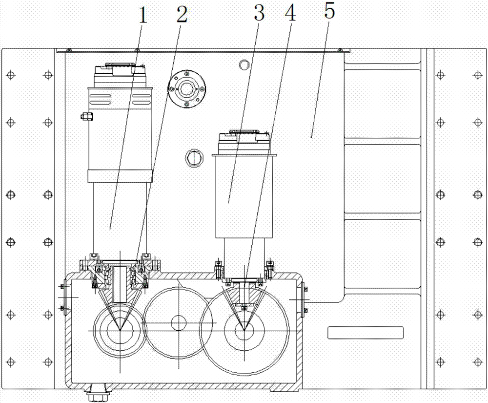
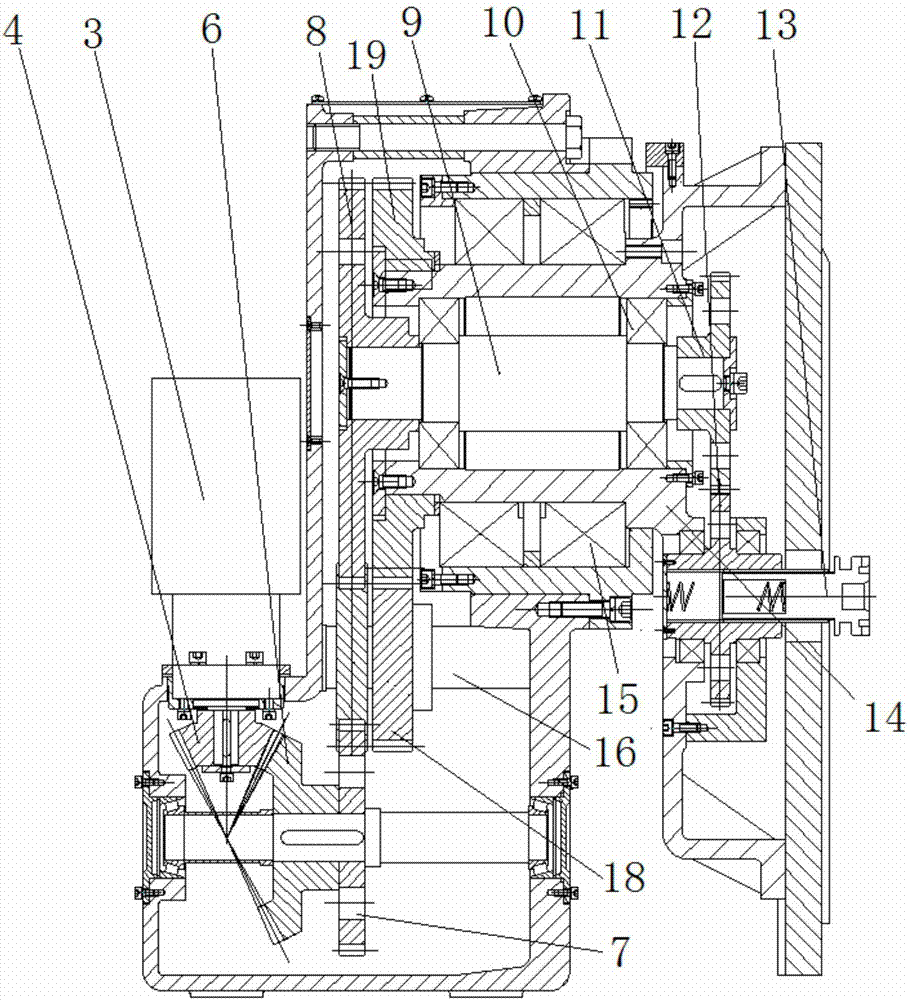
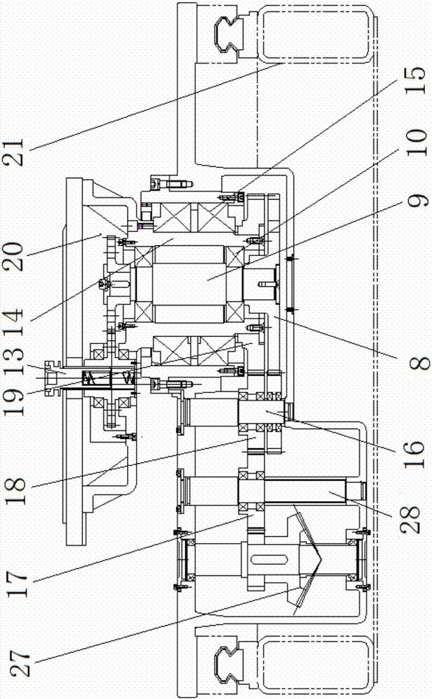
[0028] Such as Figure 1~4 As shown, the present invention includes an engine main shaft rotation driving mechanism, an engine body turning drive mechanism, a transition shaft 9, a transition sleeve 14, a turning seat 20, an engine main shaft grabbing connecting rod 13, a connecting rod driving mechanism and a box body 5. Each mechanism, the transition shaft 9, the transition sleeve 14, and the engine main shaft grabbing connecting rod 13 are all arranged in the box 5, wherein the transition sleeve 14 is supported and arranged in the box 5 through a bearing 15 , The transition shaft 9 is supported in the transition sleeve 14 through the bearing 10.

[0029] The engine main shaft rotation driving mechanism includes a rotation driving device 3 and a rotation transmission mechanism. One end of the transition shaft 9 is connected to the rotation transmission mechanism, and the rotat...


PUM


Abstract

The invention relates to the field of engine assembly, in particular to a multi-shaft rotating mechanism for engine assembly. The multi-shaft rotating mechanism comprises an engine main shaft rotary driving mechanism, an engine body turnover driving mechanism, a transition shaft, a transition shaft sleeve, a turnover seat, an engine main shaft grabbing connecting rod and a box body. The transition shaft sleeve is rotatably arranged in the box body. The transition shaft is rotatably arranged in the transition shaft sleeve. The engine main shaft rotary driving mechanism comprises a rotary driving device and a rotary transmission mechanism. One end of the transition shaft is connected with the rotary transmission mechanism, and the other end of the transition shaft is connected with the engine main shaft grabbing connecting rod through a connecting rod transmission mechanism. The engine body turnover driving mechanism comprises a turnover driving device and a turnover transmission mechanism. One end of the transition shaft sleeve is connected with the turnover transmission mechanism, and the other end of the transition shaft sleeve is connected with the turnover seat. The automation degree and the operation efficiency of a production line are greatly improved.

Description

Technical field [0001] The invention relates to the field of engine assembly, in particular to a multi-axis rotating mechanism for engine assembly. Background technique [0002] With the improvement of people's living standards, automobiles have gradually entered ordinary households, which has enabled the domestic automobile industry to maintain a momentum of rapid growth. The most important thing in the automobile manufacturing industry is the design and manufacturing of the engine production line. The traditional engine production line uses a platform assembly line operation. Since the engine needs to be rotated by ±170° for assembly, the traditional platform assembly line cannot perform the rotation function. The electric hoist had to be used to lift the engine to install screws and other operations, which caused many problems in the engine assembly process: [0003] 1. Workers frequently rotate the engine body during the assembly process, resulting in an increase in the work c...

Claims


Application Information

Patent Timeline
IPC IPC(8): B23P19/00F16H57/038
CPCB23P19/00F16H57/038
Inventor 刘俏贾阔车菲
Owner SHENYANG SIASUN ROBOT & AUTOMATION
Learn More