Hot melt adhesive injection valve

A technology of jet valve and hot melt adhesive, which is applied in the direction of coating, device for coating liquid on the surface, etc. wide range of effects

Pending Publication Date: 2019-08-16
SHENZHEN AXXON AUTOMATION
View PDF0 Cites 0 Cited by
  • Summary
  • Abstract
  • Description
  • Claims
  • Application Information

AI Technical Summary

Problems solved by technology

At present, in enterprise factories, when dispensing hot melt adhesives involved, more electronic devices are coated with needle dispensers. This dispensing method has poor precision, low efficiency, and affects the smoothness of the workpiece surface have higher requirements
In addition, due to the impact force of the injection valve used in the enterprise factory, the impact force cannot be adjusted. Most of the impact force is small and the viscosity of the hot melt adhesive is generally high, so that hot melt adhesive dispensing cannot be carried out smoothly.
The existing hot melt adhesive injection valve is suitable for the ultra-low temperature hot melt adhesive field with a heating temperature range of 90-120°C, and the application of other high-temperature section (160-180°C) hot-melt adhesive fields is still blank, so the existing Injection valves can no longer meet the demand for hot melt adhesives
[0004] In summary, the injection valves in the prior art have the following defects: the applicable heating temperature range is 90-120°C in the field of ultra-low temperature hot melt adhesives, and it is not suitable for other high temperature sections, and the application range is limited; the impact force is small and the hot melt adhesive The viscosity is generally high, so that hot melt adhesive dispensing cannot be carried out smoothly

Method used


Image

  • Hot melt adhesive injection valve
  • Hot melt adhesive injection valve
  • Hot melt adhesive injection valve

Examples


Embodiment Construction

[0026] In order to make the purpose, technical solutions and advantages of the present invention clearer, the various embodiments to be described below will refer to the corresponding drawings, and these drawings constitute a part of the embodiments, which describe various possible implementations of the present invention. kind of embodiment. It is to be understood that other embodiments may be utilized or structural and functional modifications may be made to the embodiments set forth herein without departing from the scope and spirit of the present invention.

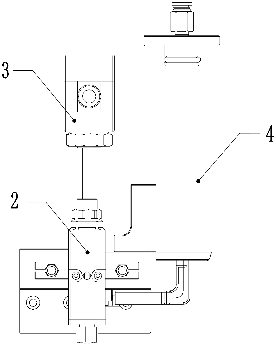
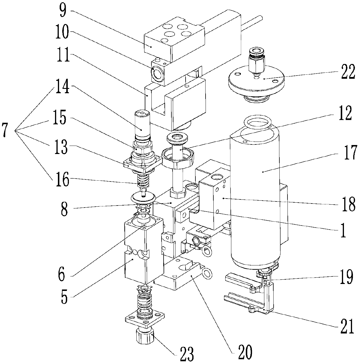
[0027] Such as Figure 1-Figure 4 Shown, the hot melt glue injection valve of the present embodiment:

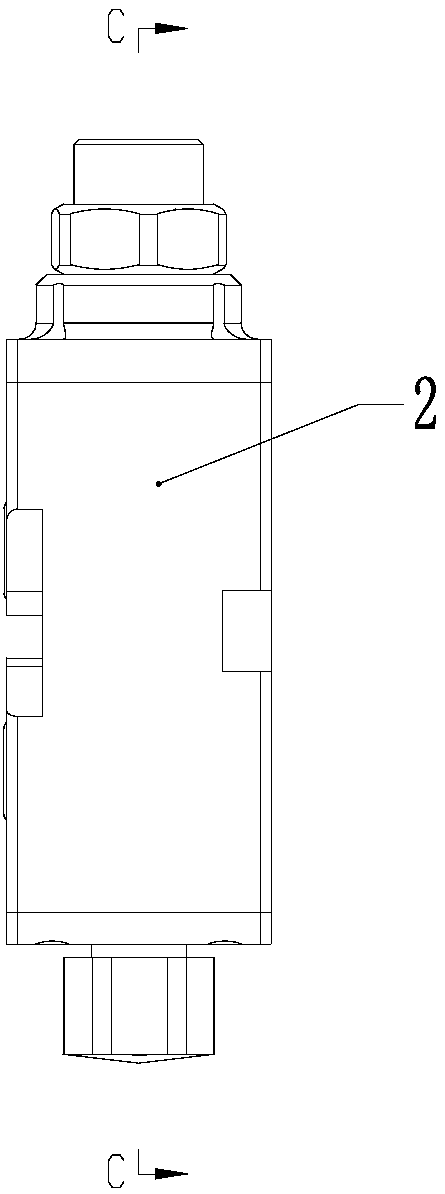
[0028] It includes a heat insulating element 1, a valve body assembly 2, and a solenoid valve assembly 3 and a heating barrel assembly 4 respectively connected to the valve body assembly 2;

[0029] The valve body assembly 2 includes a main body 5, a striker mechanism 6 pierced in the main body 5, and an adjustmen...


PUM


Abstract

The invention discloses a hot melt adhesive injection valve which comprises a heat insulation piece (1), a valve body assembly (2), an electromagnetic valve assembly (3) and a heating material barrelassembly (4). The electromagnetic valve assembly (3) and the heating material barrel assembly (4) are connected with the valve body assembly (2) correspondingly. The valve body assembly (2) comprisesa body (5), a striker mechanism (6) penetrating through the body (5) and an adjusting mechanism (7) for adjusting the impact strength of the striker mechanism (6). The electromagnetic valve assembly (3) is used for driving the striker mechanism (6) to move. The heating material barrel assembly (4) communicates with the body (5). The heat insulation piece (1) is arranged between the heating material barrel assembly (4) and the electromagnetic valve assembly (3). The hot melt adhesive injection valve has the beneficial effects that the heat insulation piece can play a heat insulation role, so that even in a high-temperature section, the heating material barrel assembly can be maintained at a proper temperature; and the adjusting mechanism can adjust the impact strength of the striker mechanism, so that the application range is wider, and hot melt adhesive dispensing can be smoothly carried out when the impact strength is increased.

Description

technical field [0001] The present invention relates to injection valves, in particular to hot melt adhesive injection valves. Background technique [0002] Hot melt adhesive (hereinafter referred to as hot melt adhesive) is a kind of plastic adhesive. Its physical state changes with temperature within a certain temperature range, but its chemical properties remain unchanged. It is non-toxic and tasteless, and is an environmentally friendly chemical product. Compared with other glues, its curing speed is faster, and it has the characteristics of melting when heated and bonding when cooled; and its performance is very stable, not affected by changes in temperature and humidity of the working environment, thus ensuring the bonding strength; at the same time, the adhesive It has a wide range of bonding objects, and no matter what kind of bonding object it is, it has high bonding strength and good sealing performance, and does not require a post-drying process, and the bonding p...

Claims


Application Information

Patent Timeline
IPC IPC(8): B05C5/02B05C11/10
CPCB05C5/0225B05C11/1042
Inventor 周晓丹陆科惠罗宇辉
Owner SHENZHEN AXXON AUTOMATION
Why Eureka
Try Eureka