
Bracket mechanism

A technology of brackets and rotating parts, which is applied in the direction of grinding workpiece brackets, grinding machine parts, and other manufacturing equipment/tools, etc. It can solve the problems of immobile fixed installation, difficulty in meeting adjustment needs, and inability to fine-tune adjustments, etc., to achieve Avoid deformation or even breakage, high adjustment accuracy

Pending Publication Date: 2019-08-16
SHENZHEN JINZHOU PRECISION TECH
View PDF0 Cites 0 Cited by
  • Summary
  • Abstract
  • Description
  • Claims
  • Application Information

AI Technical Summary

Problems solved by technology

When processing micro-drills, since the diameter of micro-drills is small and the aspect ratio (length-to-diameter ratio refers to the ratio of length to diameter) is large, if the bar cannot fit well with the bracket, it will be easily deformed or even broken.
At present, the bracket is either fixed and immovable, and cannot be adjusted; or the position is adjusted through the cylinder or oil cylinder, which cannot be fine-tuned, and it is difficult to meet the adjustment needs

Method used


Image

  • Bracket mechanism
  • Bracket mechanism
  • Bracket mechanism

Examples


Embodiment Construction

[0031] The technical solutions of the present invention will be further described below in conjunction with the accompanying drawings and through specific implementation methods.

[0032] In describing the present invention, it is to be understood that the terms "upper", "lower", "front", "rear", "left", "right", "vertical", "horizontal", "top", The orientation or positional relationship indicated by "bottom", "inner", "outer", etc. is based on the orientation or positional relationship shown in the drawings, and is only for the convenience of describing the present invention and simplifying the description, rather than indicating or implying the referred device Or elements must have a certain orientation, be constructed and operate in a certain orientation, and thus should not be construed as limiting the invention. The terms "first", "second", "third" and the like are only used for distinguishing descriptions, and should not be construed as indicating or implying relative im...


PUM


Abstract

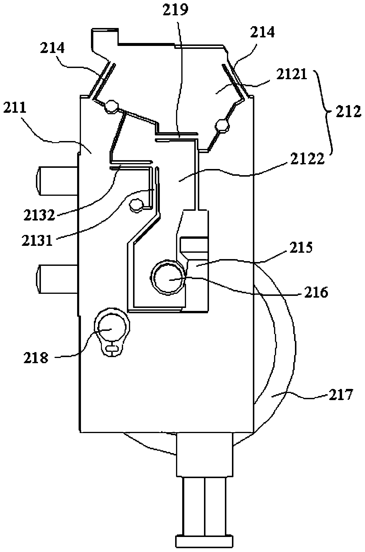
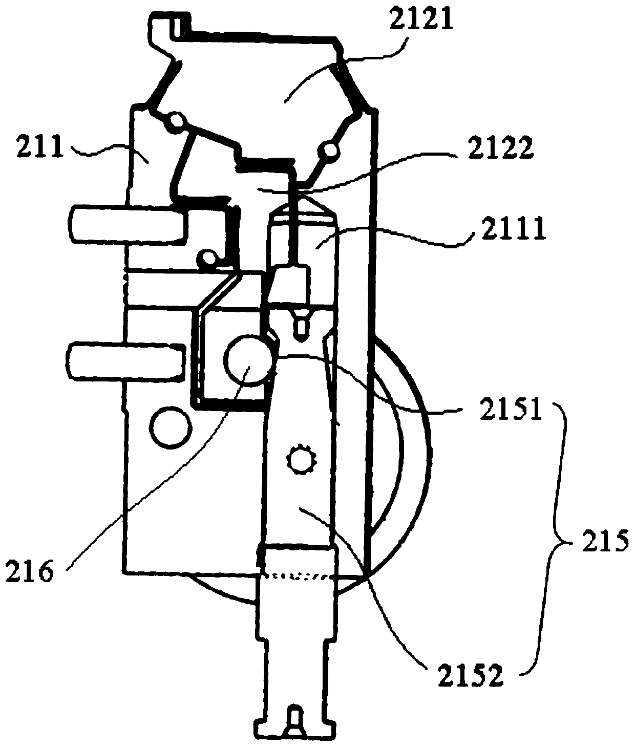
The invention discloses a bracket mechanism which comprises an adjusting base and a bracket. The adjusting base comprises a main body, a rotating portion and an adjusting part. The rotating portion iselastically connected with the main body. The adjusting part is movably arranged on the main body and arranged to be capable of providing force for enabling the rotating portion to rotate relative tothe main body. The bracket is arranged on the rotating portion. According to the bracket mechanism, the adjusting base of the bracket mechanism comprises the main body and the rotating portion whichare elastically connected, elastic force between the main body and the rotating portion can be overcome through the adjusting portion, thus the rotating portion can rotate relative to the rotating portion, the adjusting amount is small, precision micro adjustment of the angle can be achieved, the adjusting precision is high, then a part of extrusion force of a grinding wheel to a micro drill bit is offset, and the situation that the micro drill bit deforms and even breaks can be avoided.

Description

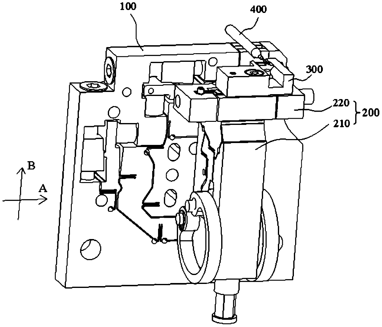
technical field [0001] The invention relates to a bracket mechanism. Background technique [0002] When tools such as grinding wheels are used to process tools, it is usually necessary to use a bracket to support the bar used to process the tool to offset part of the extrusion force of the grinding wheel. When processing micro-drills, since the diameter of micro-drills is small and the aspect ratio (the aspect ratio refers to the ratio of length to diameter) is large, if the bar cannot fit well with the bracket, it will be easily deformed or even broken. At present, the bracket is either fixed and immovable, and cannot be adjusted; or the position is adjusted by the air cylinder or oil cylinder, which cannot be fine-tuned, and it is difficult to meet the adjustment needs. Contents of the invention [0003] The purpose of the present invention is to propose a bracket mechanism that can be finely adjusted. [0004] For reaching this purpose, the present invention adopts fo...

Claims


Application Information

Patent Timeline
Patent Type & Authority Applications(China)
IPC IPC(8): B24B3/00B24B41/06B24B47/22
CPCB24B3/00B24B41/06B24B47/22
Inventor 朱建韩庆红
Owner SHENZHEN JINZHOU PRECISION TECH
Learn More