Electric bicycle riding assistance kickstand system

A technology for electric bicycles and auxiliary vehicles, which is applied to bicycle accessories, bicycle brackets, transportation and packaging, etc., can solve the problems of battery reconditioning quality, easy side slip and rollover, easy dumping, etc., to reduce the traffic accident rate, The effect of not easy to slide and roll over

Inactive Publication Date: 2019-08-16
李伟
View PDF0 Cites 2 Cited by
  • Summary
  • Abstract
  • Description
  • Claims
  • Application Information

AI Technical Summary

Problems solved by technology

[0003] 1. Sudden braking, fast turning and easy to dump in traffic accident collisions
[0004] 2. It is easy to slip and roll over in rainy and snowy weather, especially when the road is icy
[0005] 3. Due to the heavy weight of the battery and the large curb weight of the vehicle, the braking distance is relatively long, and the speed and energy of the collision are far more than that of a bicycle.
[0006] During the above-mentioned collision and rollover process, the driver and passengers fall from the vehicle, which is easy to be scratched on the road surface, and the hands and feet are easy to fall and fracture. The resulting casualties are quite serious, and the vehicle is often severely damaged.
[0007] After investigation, products or exhibits that avoid the above defects have not yet appeared. Users and car manufacturers lack a simple, practical, and low-cost "anti-rollover, brake-assisted" electric bicycle riding auxiliary support system. Actual demand

Method used


Image

  • Electric bicycle riding assistance kickstand system
  • Electric bicycle riding assistance kickstand system
  • Electric bicycle riding assistance kickstand system

Examples


Embodiment Construction

[0033] Below in conjunction with accompanying drawing, specific embodiment of the present invention is described in further detail:

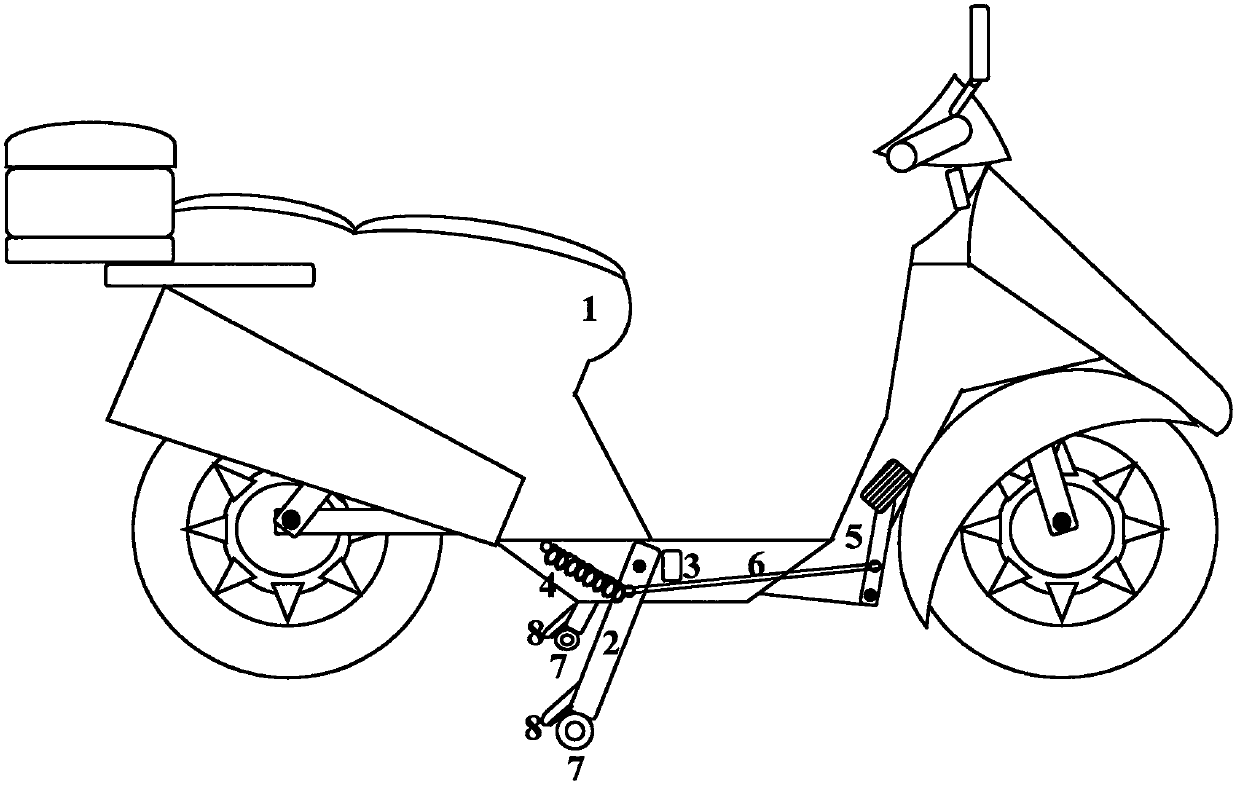
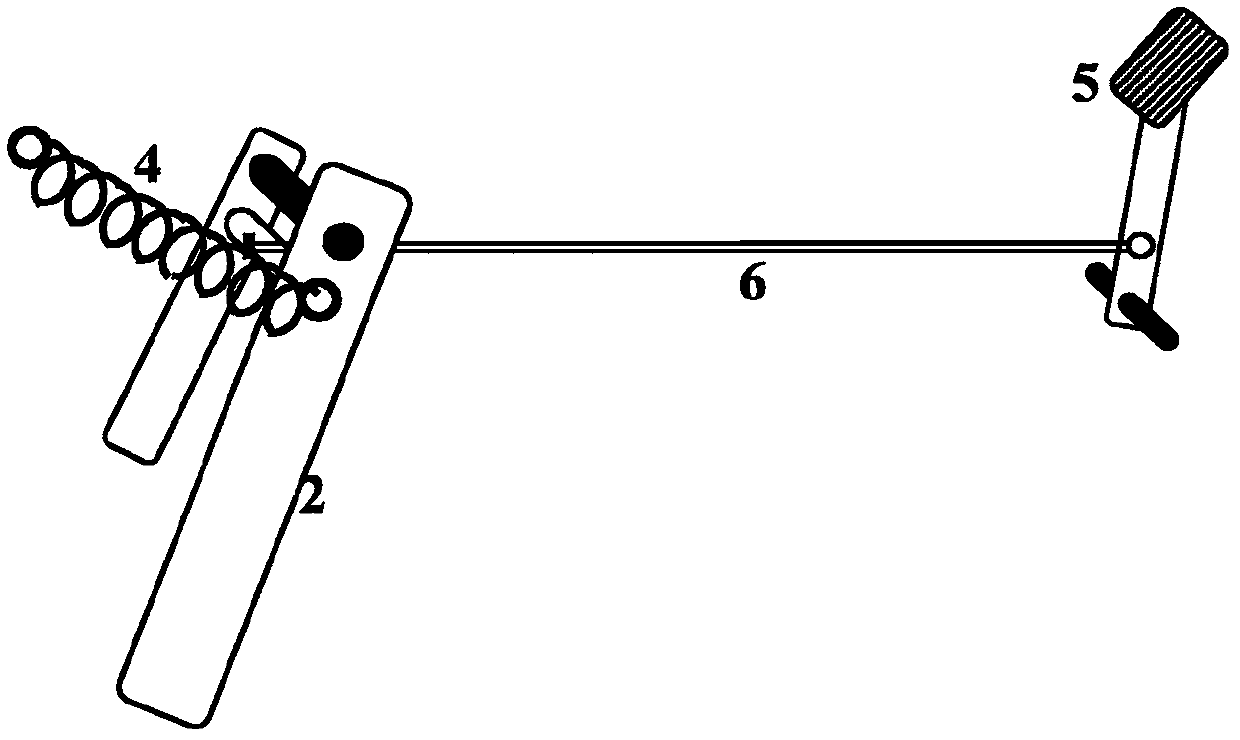
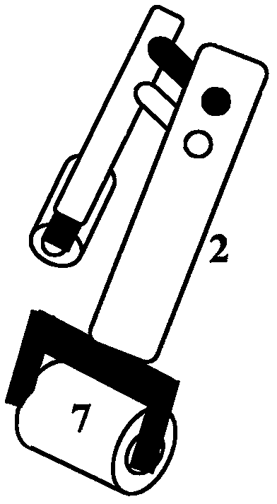
[0034] figure 1 It is the whole vehicle schematic diagram of the basic embodiment of the present invention. figure 2 It is an enlarged view of the embodiment of the device of the present invention. The basic implementation plan is: the upper end of the vehicle 1 lower part of the movable hinged vehicle support 2, the vehicle 1 in front of the vehicle 1 is provided with a limit block 3, and the lower part of the vehicle support 2 and the vehicle body of the vehicle 1 behind A return spring 4 is provided between them, and the innovation on this basis is that a pedal device 5 is also provided on the vehicle 1 to connect with the support 2; when the vehicle 1 is running, the driver steps on the pedal device At 5 o'clock, the said support 2 of its mechanical connection descends toward the ground. The vehicle 1 is moving when the support 2 is swin...


PUM


Abstract

The invention belongs to the field of vehicle kickstands, and discloses an electric bicycle riding assistance kickstand system. The electric bicycle riding assistance kickstand system aims to fundamentally solve the problem that electric bicycles and electric motorcycles are prone to falling sideways and have a long braking distance in the case of emergency braking, fast turning, wet pavement andthe like. A kickstand (2) is hinged to the lower part of a bicycle (1), the innovation is that when a pedal device (5) connected to the kickstand (2) is stepped on, the kickstand (2) is driven to swing to the ground forward and downward, a pulley (7) at the lower end of the kickstand forms a supporting surface with a front wheel and a rear wheel to play a safety support role when the bicycle (1) is running, and the bicycle is not prone to falling sideways; the kickstand (2) can further assist the braking; and when the pedal device (5) is released, a return spring (4) pulls the kickstand (2) back to the lower part of the bicycle (1). The electric bicycle riding assistance kickstand system is used for two-wheeled vehicles, can further play a support role in dynamic driving while playing a role of statically supporting the vehicle; the electric bicycle riding assistance kickstand system is mainly used for preventing falling sideways, can further shorten the braking distance, and multiplyreduces the personal property loss in the accidents, driving is simple, safe and practical, and the cost is low.

Description

technical field [0001] The invention belongs to the field of bicycle supports, and in particular relates to an electric bicycle riding auxiliary bicycle support system. Background technique [0002] In recent years, electric bicycles have been widely used for their labor-saving and quick advantages, but there are still the following disadvantages: [0003] 1. Sudden braking, fast turning and easy to dump in traffic accident collisions. [0004] 2. In rainy and snowy weather, especially when the road surface is icy, it is easy to slip and roll over. [0005] 3. Due to the heavy weight of the battery and the large curb weight of the vehicle, the braking distance is relatively long, and the speed and energy of the collision far exceed that of a bicycle. [0006] During the above-mentioned collision and rollover process, the driver and occupants fall from the car, easily scratched on the road surface, and the hands and feet are easily broken. The resulting casualties are quite...

Claims


Application Information

Patent Timeline
IPC IPC(8): B62H1/12
CPCB62H1/12
Inventor 李伟董殿伟焦晓明
Owner 李伟
Why Eureka
Try Eureka