Feeding device of textile equipment

A technology of feeding device and textile equipment, applied in thin material handling, transportation and packaging, winding strips, etc., can solve the problem that the drive and movement of the cloth winding roller cannot coexist, and achieve the effect of simple and convenient operation

Inactive Publication Date: 2019-08-16
安徽职业技术学院
View PDF15 Cites 6 Cited by
  • Summary
  • Abstract
  • Description
  • Claims
  • Application Information

AI Technical Summary

Problems solved by technology

[0005] The purpose of the present invention is to overcome the problem that the driving and movement of the cloth roller in the feeding device in the prior art cannot coexist, and to provide a feeding device for textile equipment

Method used


Image

  • Feeding device of textile equipment
  • Feeding device of textile equipment
  • Feeding device of textile equipment

Examples


Embodiment 1

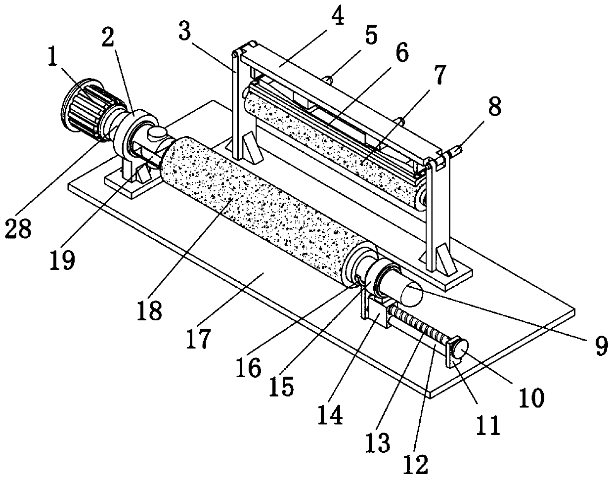
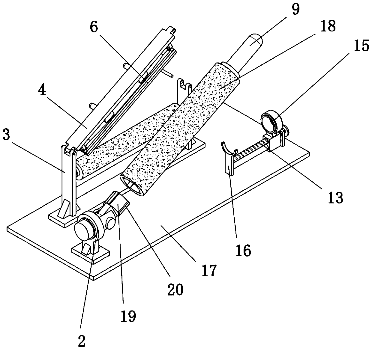
[0042] Example 1, please refer to figure 1 , figure 2 and Figure 4 , a feeding device for textile equipment, comprising a base plate 17, a cloth winding roller 18 is arranged on the top side of the bottom plate 17, a connecting pin 19 is embedded at one end of the cloth winding roller 18, and one end of the connecting pin 19 is rotated by a pin shaft Connected with a support pin 28, the connection pin 19 and the support pin 28 are perpendicular to each other, the support pin 28 can drive the connection pin 19 to rotate, and relative rotation can occur between the connection pin 19 and the support pin 28, wherein the support pin 28 is supported by The sleeve 2 is rotationally connected with the base plate 17, the support pin 28 is rotationally connected with the support sleeve 2 through a bearing sleeve, and the other end is fixedly connected with the limit shaft 9, and one end of the support pin 28 is transmission-connected with the output shaft of the drive motor 1, wherei...

Embodiment 2

[0043] Example 2, please refer to figure 1 and figure 2, the bottom of the limit shaft 9 is provided with a threaded rod 13, one end of the threaded rod 13 is rotatably connected to the clamping plate 16 through a rotating shaft, relative rotation can occur between the threaded rod 13 and the clamping plate 16, and the other end runs through the fixing plate 11, And the extension end is fixedly connected with the turntable 10, the operator drives the threaded rod 13 to rotate by turning the turntable 10, the top of the clamping plate 16 has a semi-circular arc structure, and the semi-arc structure realizes the function of the limit clamp 15 and the limit pin. 9 After separation, the stopper pin can be supported by the clamping plate 16, and the top wall of the clamping plate 16 is attached to the outer wall of the limit shaft 9, and the threaded rod 13 is sleeved with a threaded sliding sleeve 14, and the threaded rod 13 It is connected with the threaded sliding sleeve 14 by...

Embodiment 3

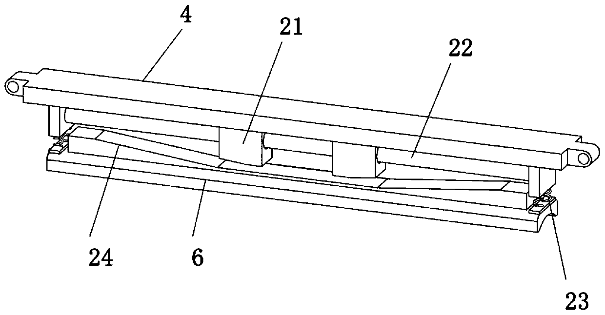
[0044] Example three, please refer to Figure 1-5 , the top of the bottom plate 17 and the opposite side of the cloth roll 18 are provided with a limit roller 7, and the two ends of the limit roller 7 are rotatably connected with the base plate 17 through the support plate 3, wherein the two ends of the limit roller 7 are connected to each other through the rotating shaft. The support plate 3 is rotatably connected, and through the setting of the limit roller 7, the friction between the cloth and the support plate 3 during the supply process is reduced to ensure the quality during transportation. A movable cover is set directly above the limit roller 7 4. One end of the movable cover 4 is rotatably connected to the support plate 3 through the pin shaft, and the other end is rotatably connected to the support plate 3 through the pull pin 8, realizing the function that the movable cover 4 can rotate around the top of the support plate 3 through the pin shaft , wherein the plug-i...


PUM


Abstract

The invention discloses a feeding device of textile equipment. The feeding device comprises a bottom plate, wherein a cloth winding roller is arranged on one side of the top of the bottom plate, and one end of the cloth winding roller is provided with a connecting pin in an embedded mode; and one end of the connecting pin is rotationally connected to a supporting pin through a pin shaft, the supporting pin is rotationally connected to the bottom plate through a supporting sleeve, the other end of the connecting pin is fixedly connected to a limiting shaft, and a threaded rod is arranged at thebottom of the limiting shaft. According to the feeding device of textile equipment, when the cloth winding roller needs to be disassembled or installed, a limiting hoop is driven to move through a rotating disc and the threaded rod, so that the limiting hoop is separated from the limiting shaft, then the cloth winding roller is inclined through lifting of the limiting shaft, and the cloth windingroller is pulled out; and if the installation is needed, the steps are operated in the reverse mode so that the cloth winding roller can be disassembled and installed, in the operation process, the rotating disc is controlled to limit the cloth winding roller, and the operation is simple and convenient.

Description

technical field [0001] The invention relates to the field of textile equipment, in particular to a feeding device for textile equipment. Background technique [0002] Textile industry in our country is a highly labor-intensive and foreign-dependent industry. my country is the world's largest producer and exporter of textiles and clothing. The sustained and stable growth of textiles and clothing exports is crucial to ensuring my country's foreign exchange reserves, balance of payments, stability of the RMB exchange rate, social employment and sustainable development of the textile industry. The raw materials of textiles mainly include cotton, cashmere, wool, cocoon silk, chemical fiber, feather and down, etc. The downstream industries of the textile industry mainly include clothing, home textiles, and industrial textiles. [0003] The textile industry needs to use the feeding device to feed the cloth in the actual production process. However, the existing feeding device sti...

Claims


Application Information

Patent Timeline
Patent Type & Authority Applications(China)
IPC IPC(8): B65H18/10B65H18/26
CPCB65H18/10B65H18/26
Inventor 瞿永
Owner 安徽职业技术学院
Why Eureka
Try Eureka