Built-in accommodating groove type electric melting pipe fitting

A technology of electrofusion pipe fittings and holding tanks, which is applied in the direction of pipes/pipe joints/pipe fittings, pipe connection layout, mechanical equipment, etc., which can solve the problems of poor firmness and achieve the effects of convenient alignment and fixing, simple molds, and convenient production

Inactive Publication Date: 2019-08-16
优捷特环保科技有限公司
View PDF9 Cites 3 Cited by
  • Summary
  • Abstract
  • Description
  • Claims
  • Application Information

AI Technical Summary

Problems solved by technology

[0005] The object of the present invention is to provide a built-in accommodation groove type electrofusion pipe fitting, which adopts the end face wall of the end to be inwardly recessed to form several accommodation grooves, and the accommodation grooves have multiple connecting surfaces, which have high firmness; Fused pipe fittings adopt single-sided fusion connection, and the connection surface has only one side, which has the defect of poor firmness

Method used


Image

  • Built-in accommodating groove type electric melting pipe fitting
  • Built-in accommodating groove type electric melting pipe fitting
  • Built-in accommodating groove type electric melting pipe fitting

Examples


Embodiment 1

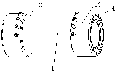
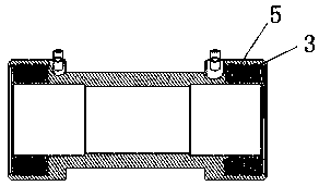
[0052] Such as figure 1 with figure 2 As shown, the present invention discloses a built-in accommodating tank type electrofusion pipe fitting, which includes a pipe body 1 and eight lugs 2 arranged on the pipe body, and the pipe body includes two ends 11 and a first heating wire 3 , the end face walls of both ends are inwardly recessed to form an integral annular accommodation groove 4; the first hot-melt material layer 5 is fixed on the outer surface of the accommodation groove and the inner surface of the accommodation groove; and the first heating wire It is fixed in the first hot-melt material layer; the two ends of the first heating wire are respectively electrically connected to the terminal. The terminal is arranged on the outer wall of the end of the pipe body. The terminals are all installed at the end away from the nozzle. The outer diameters of the two ends of the pipe body are smaller than the outer diameter of the middle part. The included angle between the c...

Embodiment 2

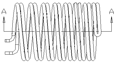
[0056] Such as Figure 4 , Figure 5 ; The difference between Embodiment 2 and Embodiment 1 is that a built-in accommodation tank type electrofusion pipe fitting includes a pipe body and eight terminals arranged on the pipe body, and the pipe body includes two ends and a first heating wire 3. The end walls of both ends are inwardly recessed to form an integral annular accommodation groove 4; the first hot-melt material layer 5 is fixed on the outer surface of the accommodation groove and the inner surface of the accommodation groove; and the first electric heater The wire is fixed in the first heat-melt material layer; both ends of the first heating wire are electrically connected to the terminal head respectively. A second hot-melt material layer 6 is fixed on the inner wall surface of the pipe body, and a second heating wire 7 is fixed on the second hot-melt material layer, and the second heating wire is externally connected to a terminal. There are two pairs of terminals,...

Embodiment 3

[0058] Such as Image 6 , Figure 7 , Figure 8 As shown, the difference between embodiment 2 and embodiment 1 is that the outer diameters at both ends of the tube body are larger than the outer diameter at the middle. The angle between the centerlines of the two ends is 180°. Both ends are provided with annular receiving grooves.


PUM


Abstract

The invention provides a built-in accommodating groove type electric melting pipe fitting. The built-in accommodating groove type electric melting pipe fitting comprises a pipe body, at least two connection heads, first hot melt material layers and a first electric heating wire; the pipe body comprises a plurality of end heads; the end surface wall of at least one of the end heads is recessed inwards to form a plurality of accommodating grooves; the at least two connection heads are arranged on the pipe body; the first hot melt material layers are at least partially fixed to the outer surfacesof the accommodating grooves and / or on the inner surfaces of the accommodating grooves; the first electric heating wire is fixed in the first hot melt material layers; and the two ends of the first electric heating wire are electrically connected with the connection heads correspondingly. In the first aspect, the accommodating grooves are in fusion connection with a pipeline, and the built-in accommodating groove type electric melting pipe fitting is provided with a plurality of connection surfaces, so that the firmness of the built-in accommodating groove type electric melting pipe fitting is much higher than that of existing products.

Description

technical field [0001] The invention relates to the field of electric fusion pipe fittings, in particular to a built-in containing groove type electric fusion pipe fitting. Background technique [0002] At present, electrofusion pipe fittings refer to pipe fittings that use the high temperature generated by electric current to melt multiple polyethylene pipe fittings that are in contact with each other and connect them together. Compared with traditional pipe fittings, such as threaded connections and plug-in connections, due During the connection process, it is necessary to rotate or apply force to the pipe fittings. For some large pipe fittings, the on-site construction operation is very difficult. The electrofusion connection method has outstanding advantages in construction engineering. For polyethylene pipe fittings, the use of electrofusion welding technology can easily Connect the two fittings. [0003] In recent years, electrofusion pipe fittings have been widely us...

Claims


Application Information

Patent Timeline
Patent Type & Authority Applications(China)
IPC IPC(8): F16L47/03
CPCF16L47/03
Inventor 刘向东聂辉
Owner 优捷特环保科技有限公司
Why Eureka
Try Eureka