
Heat pipe and heat exchanger

A technology of heat exchangers and heat pipes, which is applied in the field of heat exchangers and heat pipes, can solve the problems of prone to bursting, increasing the pressure of the water tank, and bursting of the water tank, and achieve the effect of saving the water tank

Pending Publication Date: 2019-08-16
广东棣浩智能科技有限公司
View PDF0 Cites 0 Cited by
  • Summary
  • Abstract
  • Description
  • Claims
  • Application Information

AI Technical Summary

Problems solved by technology

[0004] (2) When the existing heat pipes are applied to heat exchangers and other equipment to realize the recovery and utilization of the heat of the oven flue gas, a water tank with cooling liquid is additionally equipped to receive the released heat, and the heat pipes are welded on the On the water tank, in this way, when the cooling liquid in the water tank absorbs heat and evaporates, the pressure of the water tank is increased, which may easily cause the water tank to burst; at the same time, when the external equipment supplies water to the water tank, a certain pulse is caused in the water tank, resulting in the above-mentioned Bursts are prone to occur in places where the stress is concentrated such as welding, and there are certain safety hazards

Method used


Image

  • Heat pipe and heat exchanger
  • Heat pipe and heat exchanger
  • Heat pipe and heat exchanger

Examples


Embodiment Construction

[0027] Below, the present invention will be further described in conjunction with the accompanying drawings and specific implementation methods. It should be noted that, under the premise of not conflicting, the various embodiments described below or the technical features can be combined arbitrarily to form new embodiments. .

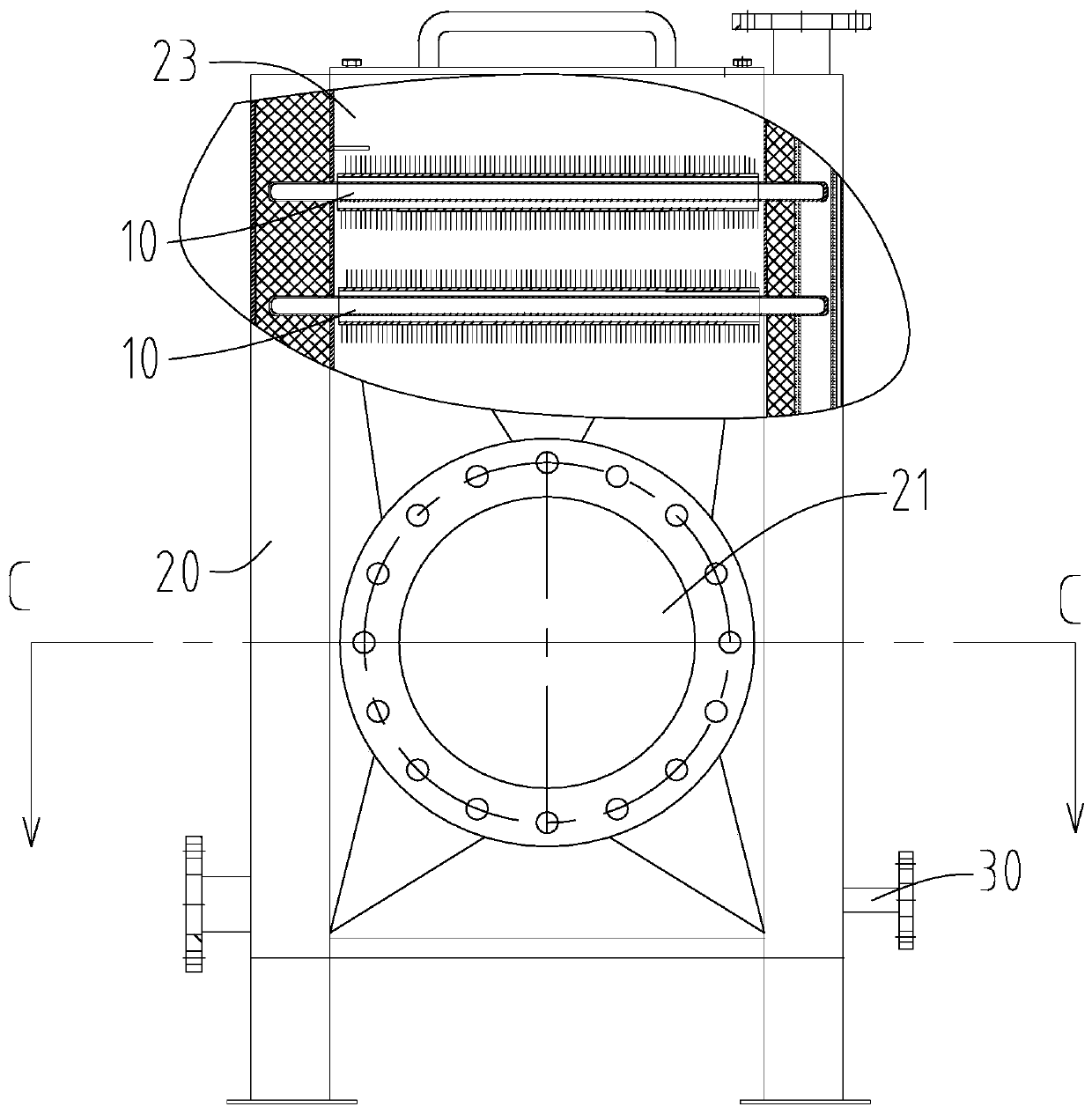
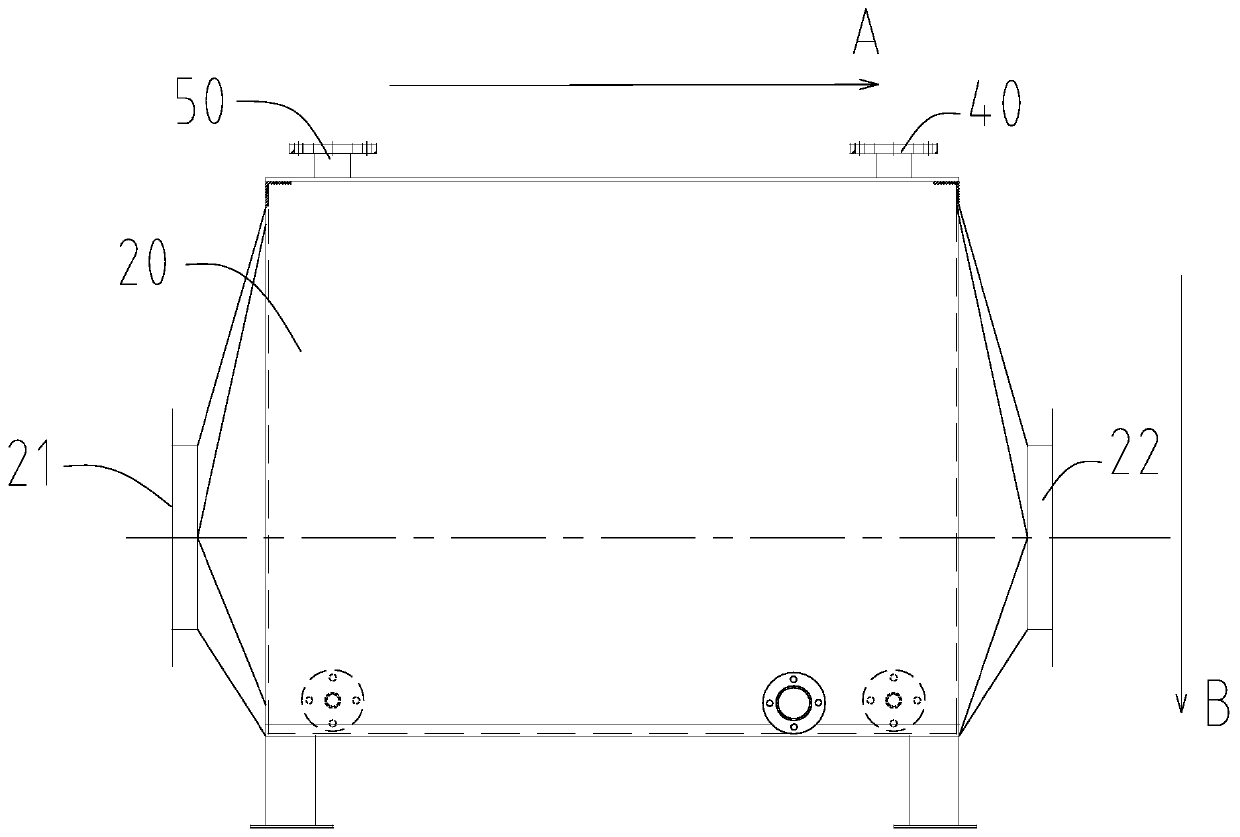
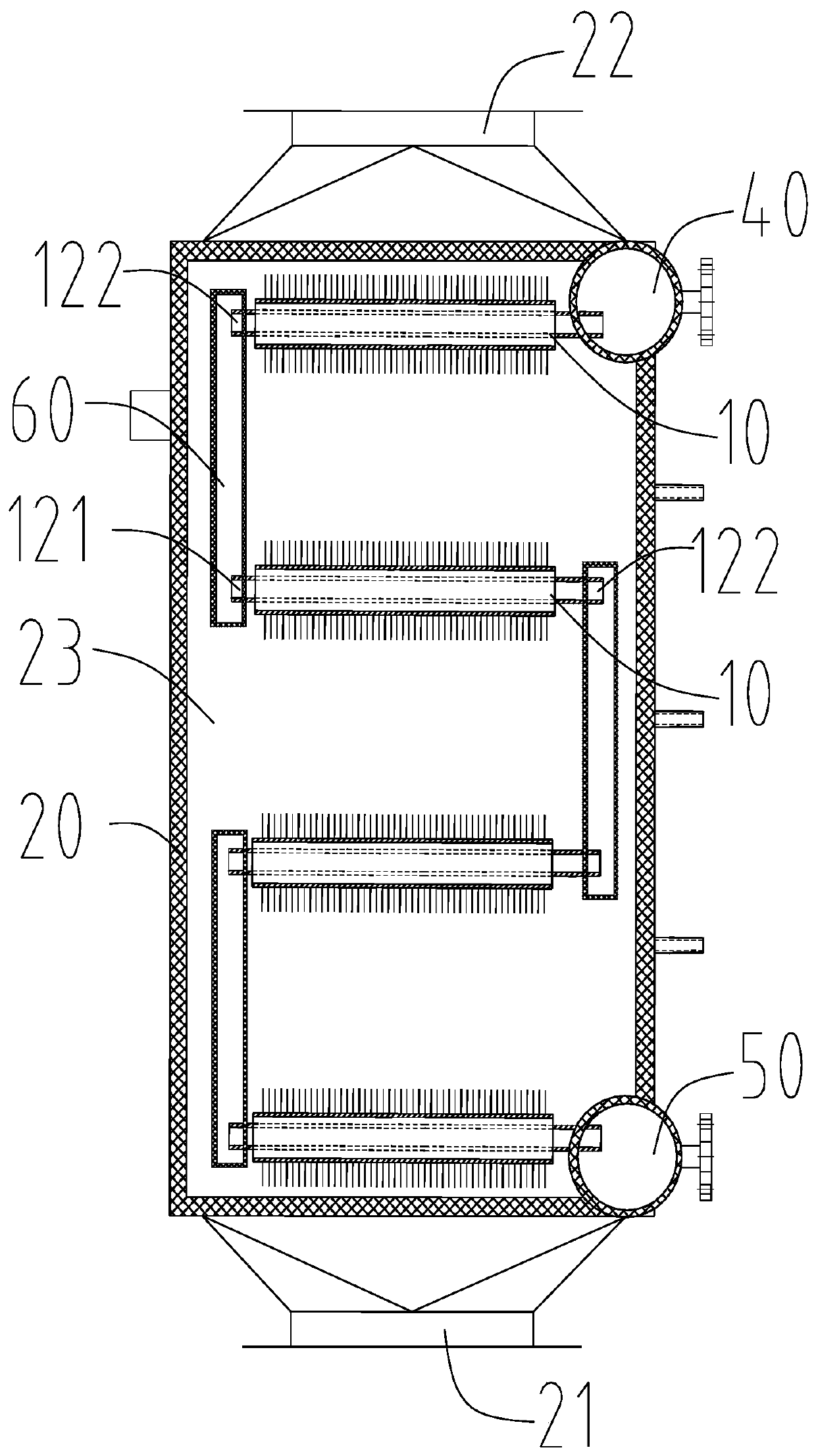
[0028] like Figure 4 The shown heat pipe 10 includes an outer tube body 11 and an inner tube body 12; the inner tube body 12 is penetrated in the outer tube body 11 and is formed with a cooling channel 123 for the passage of an external cooling liquid; the inner tube body The opposite ends of the body 12 protrude out of the outer tube body 11 respectively, and are respectively formed with a liquid inlet 121 and a liquid outlet 122; For external cooling liquid to enter and exit the cooling channel 123, the cooling liquid can be water or the like; a vacuum cavity 13 is formed between the inner tube body 12 and the outer tube body 11, and the vacuum cav...


PUM


Abstract

The invention discloses a heat pipe. The heat pipe comprises an outer pipe body and an inner pipe body, the inner pipe body is arranged in the outer pipe body in a penetrating manner, and a cooling channel allowing outer cooling liquid to pass through is formed; two opposite ends of the inner pipe body extend out of the outer pipe body, and a liquid inlet and a liquid outlet are correspondingly formed; the liquid inlet and the liquid outlet communicate with the cooling channel, a vacuum cavity is formed in the gap between the inner pipe body and the outer pipe body, and a working medium is injected into the vacuum cavity. According to the heat pipe, a liquid absorbing core and a water tank can be omitted, and the safety hidden danger of burst and the like when the heat pipe is applied to aheat exchanger and other devices can be avoided. The invention further discloses the heat exchanger.

Description

technical field [0001] The invention relates to a heat conduction device, in particular to a heat pipe and a heat exchanger. Background technique [0002] At present, heat pipes are used in a wide range of applications. They were first used in the aerospace field, and are now widely used in various heat exchangers, coolers, natural geothermal energy, etc., and play the role of rapid heat conduction; a general heat pipe consists of a tube shell and Composed of a liquid-absorbing core, wherein the inside of the tube shell is pumped into a negative pressure state, the liquid-absorbing core is set in the tube shell, and the tube shell is filled with liquid; when in use, the external heat medium is in contact with one end of the heat pipe, and one end of the heat pipe is heated, and the liquid Rapidly evaporates to form steam, and the steam flows to the other end of the heat pipe under a small pressure difference, and releases heat, recondenses into a liquid, and the liquid flows...

Claims


Application Information

Patent Timeline
IPC IPC(8): F28D15/02
CPCF28D15/02
Inventor 郭平廖燕辉崔亚楠
Owner 广东棣浩智能科技有限公司
Learn More