
Microseismic source positioning method based on first arrival time difference and waveform superposition

A seismic source positioning and microseismic technology, applied in the field of petroleum geophysical exploration and development, can solve problems such as large amount of calculation, low positioning efficiency, and large background noise, and achieve the effects of improving accuracy, improving convergence, and enhancing anti-noise ability

Active Publication Date: 2019-08-16
YANGTZE UNIVERSITY
View PDF11 Cites 17 Cited by
  • Summary
  • Abstract
  • Description
  • Claims
  • Application Information

AI Technical Summary

Problems solved by technology

However, in real-time hydraulic fracturing monitoring operations, the collected microseismic data may have characteristics such as low signal-to-noise ratio, weak energy, and large background noise, which greatly affects the accuracy of first-arrival picking.
The positioning method based on the travel time information objective function is more sensitive to the first arrival error, while the positioning method based on the waveform information objective function does not require accurate first arrival time, but its calculation is huge, resulting in low positioning efficiency

Method used


Image

  • Microseismic source positioning method based on first arrival time difference and waveform superposition
  • Microseismic source positioning method based on first arrival time difference and waveform superposition
  • Microseismic source positioning method based on first arrival time difference and waveform superposition

Examples


Embodiment

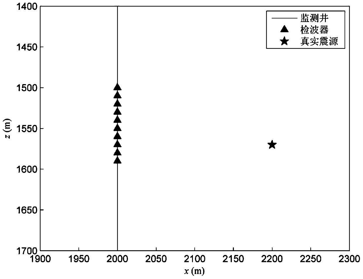
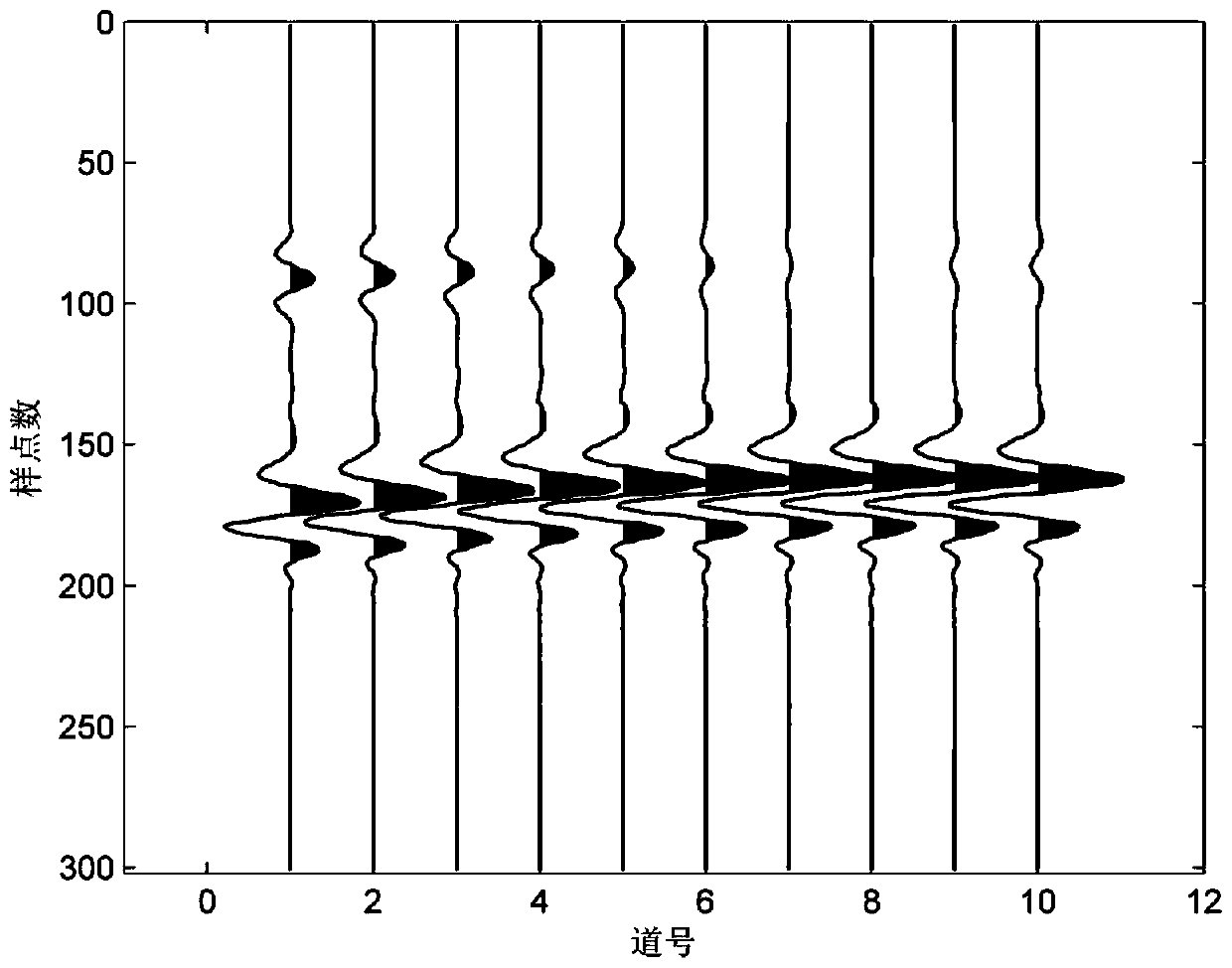
[0057] Embodiment: first establish a two-dimensional microseismic borehole observation system based on a homogeneous medium model, the longitudinal wave velocity Vp=4500m / s, the shear wave velocity Vs=2500m / s, and the density is 2.425g / cm 3 . Such as figure 2 As shown, the depth z of the 10-level geophones in the monitoring well (vertical well) at the horizontal distance x = 2000m is located at 1500-1590m respectively, and the track spacing is 10m. Set the location where the microseismic source occurs as (x, z) = (2200, 1570) m. Then, the 100Hz Reich wavelet is used to carry out the forward modeling of the two-dimensional elastic wave equation, and the sampling interval is 0.5ms, and the z-component seismic records of the theoretical model are obtained ( Figure 3a ), Figure 3b is true Figure 3a The z-component seismic record of the theoretical model after adding random noise.

[0058] In order to test the stability of the method of the present invention to the first a...


PUM


Abstract

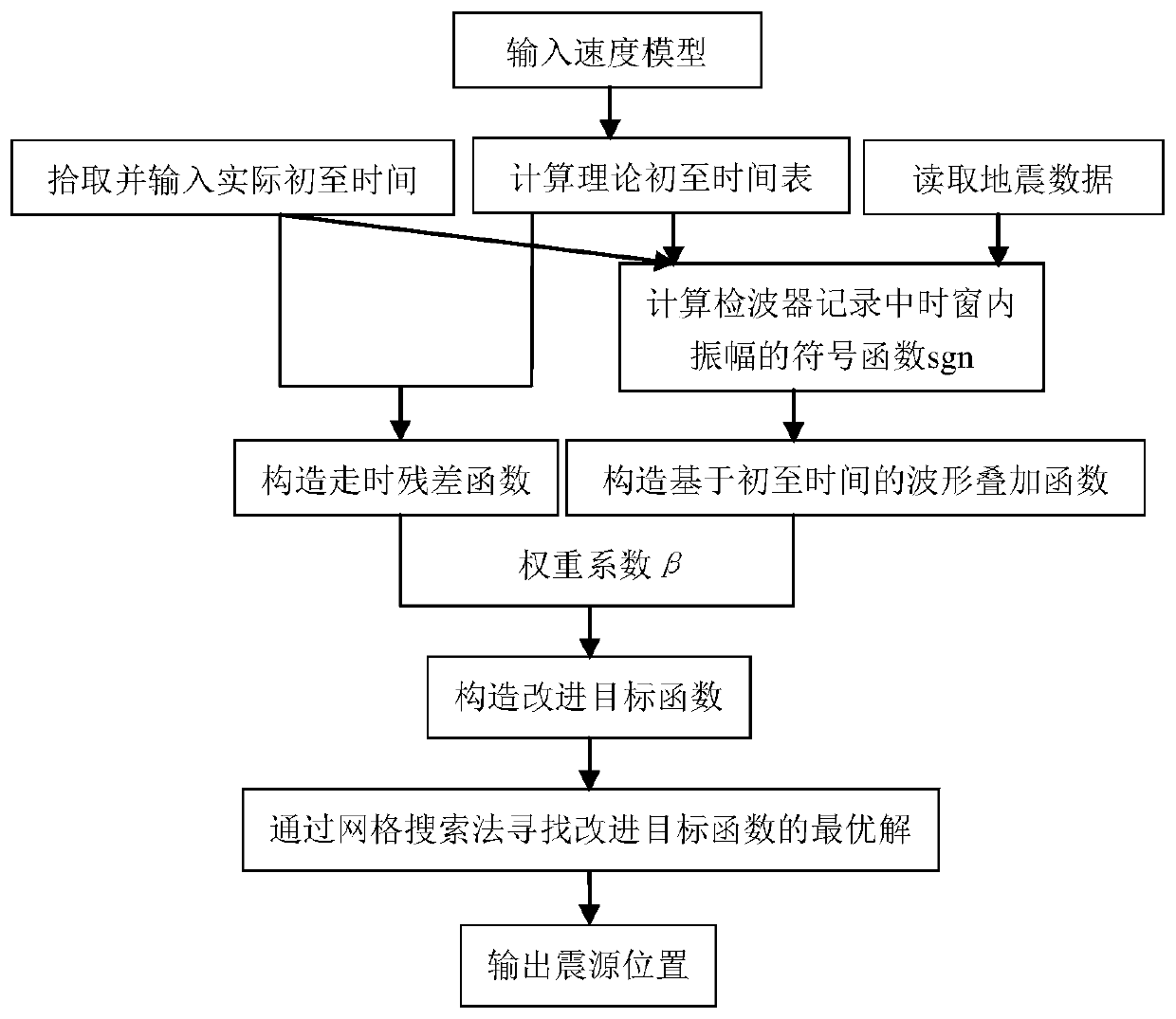
The invention provides a microseismic source positioning method based on a first arrival time difference and waveform superposition. The method comprises the following steps: S1: inputting a velocitymodel; S2: picking up and inputting an actual first arrival time, and reading seismic data; S3: calculating a theoretical first arrival time table of all mesh points in a feasible solution area to each detector according to the velocity model in S1; S4: constructing a travel time residual function Tr; S5: constructing a waveform superposition function Ews; S6: inputting a weight coefficient beta,and constructing an improved objective function according to the travel time residual function Tr in S4 and the waveform superposition function Ews in S5; and S7: finding a minimum value of the improved objective function through a grid search method, and the corresponding optimal solution being the seismic source location. According to the microseismic source positioning method provided by the invention, in view of the problem that the positioning method based on the travel time objective function is sensitive to the first arrival error, the improved objective function is constructed in combination with the first arrival time difference and the waveform superposition information, so that the anti-noise ability of the positioning method can be enhanced, the convergence of the inversion method can be improved, and the microseismic source positioning accuracy can be improved as a result.

Description

technical field [0001] The invention belongs to the technical field of petroleum geophysical exploration and development, and in particular relates to a microseismic source positioning method based on first arrival time difference and waveform superposition. Background technique [0002] Hydraulic fracturing microseismic monitoring technology is a reservoir geophysical technology to monitor the stimulation and effect of unconventional reservoirs such as tight oil and gas and shale gas. Its application results can evaluate fracturing effects, adjust fracturing design and well pattern layout, and Provide effective guidance for the next step of development, so as to increase the productivity of unconventional oil and gas reservoirs. [0003] In the processing of hydraulic fracturing monitoring data, the core part is microseismic source location. Predecessors basically use a single traveltime information or waveform information to establish an objective function, which can be d...

Claims


Application Information

Patent Timeline
Patent Type & Authority Applications(China)
IPC IPC(8): G01V1/28
CPCG01V1/288
Inventor 毛庆辉王鹏桂志先陈波
Owner YANGTZE UNIVERSITY
Learn More