Laser scanning unit and laser printer

A laser scanning and laser beam technology, applied in optical components, optics, instruments, etc., can solve problems such as unfavorable layout of internal components of the printer, unfavorable miniaturization of printing equipment, and large overall size, etc., to achieve optimal layout design and overall size. Reduce and reduce the effect of structural materials

Inactive Publication Date: 2019-08-16
至像科技有限公司
View PDF7 Cites 3 Cited by
  • Summary
  • Abstract
  • Description
  • Claims
  • Application Information

AI Technical Summary

Problems solved by technology

[0005] Therefore, the technical problem to be solved by the present invention is to overcome the problem in the prior art that the omission of the FTL lens will lead to a larger overall size, which is not conducive to the miniaturization of printing equipment, and is not conducive to the internal components of the printer. layout and other defects, thereby providing a laser scanning unit and a laser printer

Method used


Image

  • Laser scanning unit and laser printer
  • Laser scanning unit and laser printer

Examples


Embodiment Construction

[0021] The technical solutions of the present invention will be clearly and completely described below in conjunction with the accompanying drawings. Apparently, the described embodiments are some of the embodiments of the present invention, but not all of them. Based on the embodiments of the present invention, all other embodiments obtained by persons of ordinary skill in the art without making creative efforts belong to the protection scope of the present invention.

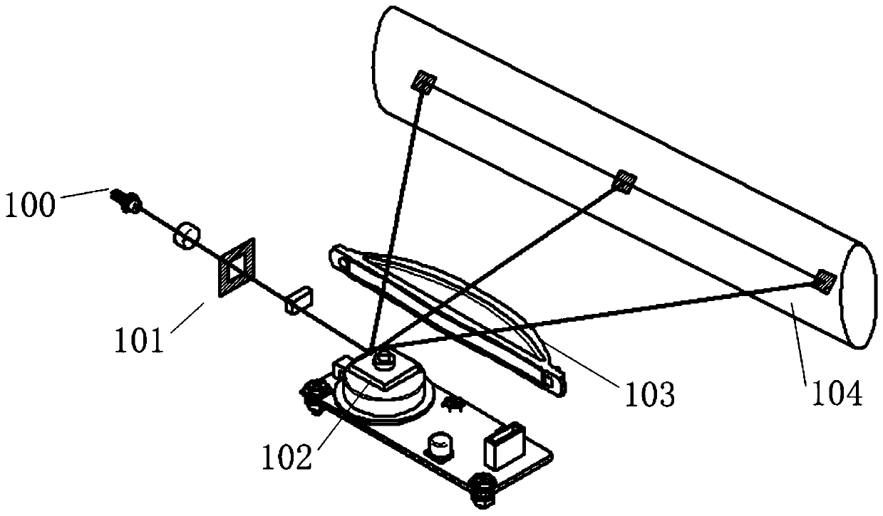
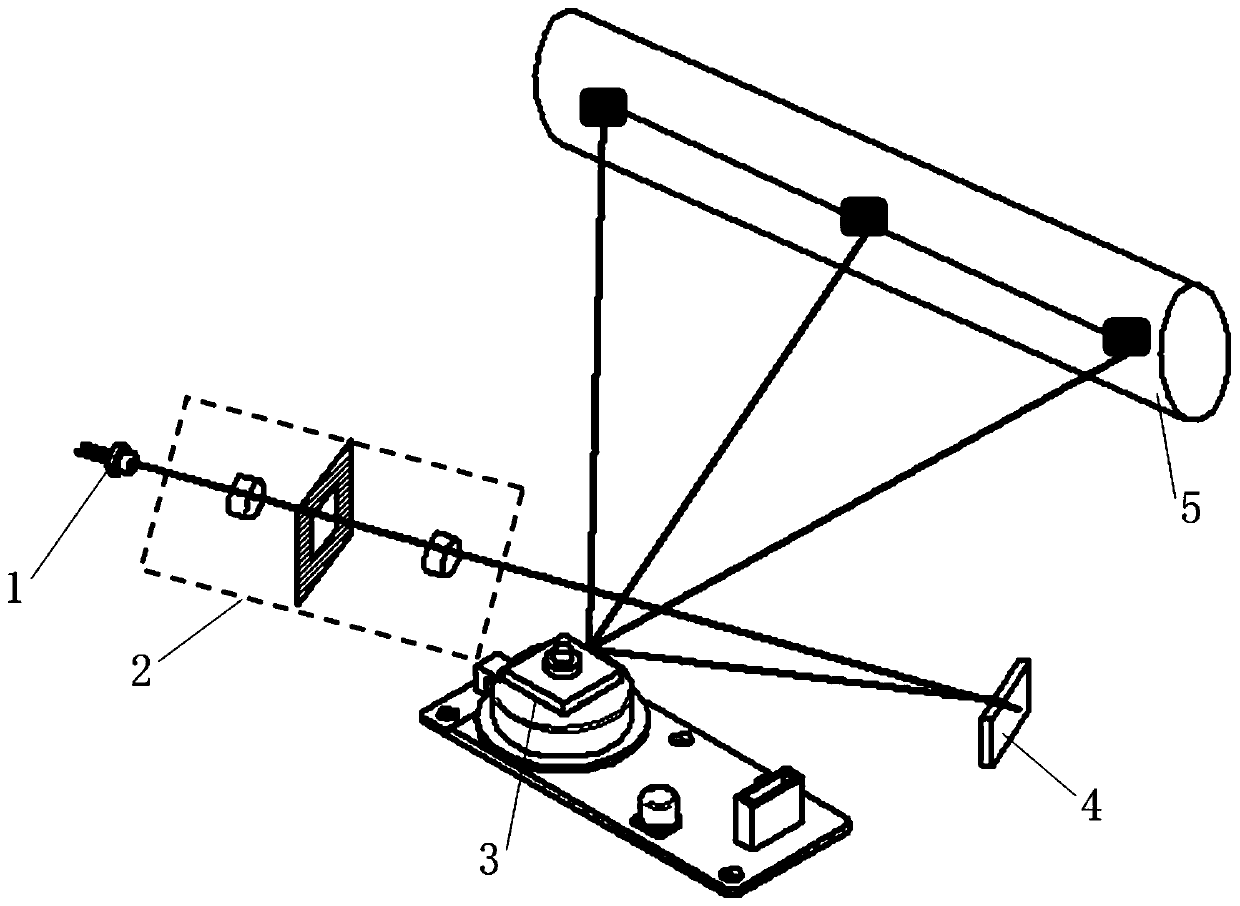
[0022] figure 2 A laser scanning unit provided by the present invention is shown. The laser scanning unit includes a laser generator (LD) 1 , a lens group 2 , a polygon mirror motor 3 , a reflection mirror 4 and an optical receiving surface (OPC) 5 arranged along an optical path.

[0023] Wherein, the laser beam emitted by the laser generator 1 reaches the polygon mirror motor 3 through the lens group 2 and the reflection mirror 4 . Using the designed mirror, the laser beam is folded. Reflect the laser bea...


PUM


Abstract

The present invention provides a laser scanning unit and a laser printer. The laser scanning unit comprises a laser generator disposed along an optical path, a lens group, a polygon motor, and a lightreceiving surface; and at least one reflecting mirror for folding laser beams is disposed between the lens group and the polygon motor. The unit folds the laser beams by adding one or more reflectingmirrors, ensures optical characteristics while optimizing component layout design, can greatly reduce overall size, and can reduce structure materials and save costs. The overall size is reduced, which is more conducive to the miniaturization and lightweight design of the whole machine. The unit makes overall size smaller, and is more advantageous for miniaturization and lightweight design of thewhole machine.

Description

technical field [0001] The invention relates to the technical field of laser scanning devices, in particular to a laser scanning unit and a laser printer. Background technique [0002] In current laser printers, the laser unit mostly adopts a laser scanning unit (LSU) and a laser matrix (LPH). Such as figure 1 As shown, the laser scanning unit on the market includes a laser generator (LD) 100 , a collimator lens group 101 , a polygon mirror motor 102 , an FTL lens 103 and an optical receiving surface (OPC) 104 . The laser beam emitted by the laser generator is a divergent beam. The divergent beam passes through the collimator lens group and focuses on the mirror surface of the polygon mirror motor once; the laser light reflected by the polygon mirror motor diverges, passes through the FTL lens, and is focused on the surface of the light-receiving surface for the second time. Focus to form a spot. The photosensitive coating on the surface of the light-receiving surface rec...

Claims


Application Information

Patent Timeline
Patent Type & Authority Applications(China)
IPC IPC(8): G02B26/12G02B17/02G02B17/06G03G15/04
CPCG02B17/023G02B17/06G02B26/124G03G15/0409
Inventor 唐波炯蒋维
Owner 至像科技有限公司
Why Eureka
Try Eureka