Driving assistance information display method based on dynamic probability driving map

A technology for driving assistance and information display, which is used in the generation of 2D images, combustion engines, and image data processing.

Active Publication Date: 2019-08-16
JILIN UNIV
View PDF7 Cites 22 Cited by
  • Summary
  • Abstract
  • Description
  • Claims
  • Application Information

AI Technical Summary

Problems solved by technology

[0003] The present invention provides a method for displaying driving assistance information based on a dynamic probabilistic driving map in order to solve the problem that the existing

Method used


Image

  • Driving assistance information display method based on dynamic probability driving map
  • Driving assistance information display method based on dynamic probability driving map
  • Driving assistance information display method based on dynamic probability driving map

Examples


specific Embodiment approach 1

[0068] Specific implementation mode 1. Combination Figure 1 to Figure 17 Describe this embodiment, a method for displaying driving assistance information based on a dynamic probabilistic driving map, which is implemented by the following steps:

[0069] Step 1. Generate an initial static grid map: use the camera and inertial navigation device to obtain lane line information by building a lane line model; use laser radar to obtain obstacle information and fill it into the grid map.

[0070] The method of generating the initial static grid map is as follows:

[0071] Step 11, establishing a lane line model and obtaining lane line information;

[0072] Use the on-board smart camera for lane mark detection and lane tracking to realize the grid division of the surrounding environment of the vehicle and vehicle positioning and other functions.

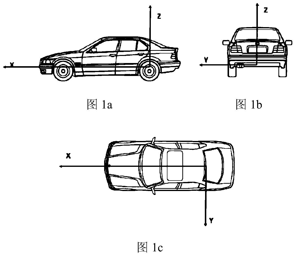
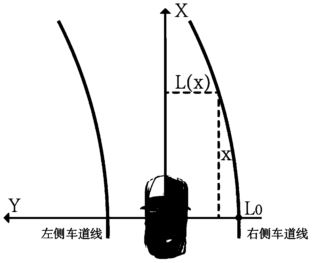
[0073] Based on the vehicle coordinate system, such as figure 1 shown. Assume that the four-lane boundary recognized by the smart came...

specific Embodiment approach 2

[0171] Specific embodiment two, combine Figure 1 to Figure 17 Describe this embodiment. This embodiment is a driving assistance information system supported by a dynamic probabilistic driving map based on the driving assistance information display method based on a dynamic probabilistic driving map described in Embodiment 1;

[0172] Firstly, the spatial position information and motion information of the vehicle are obtained through the vehicle sensors such as inertial navigation and GPS, and the obstacle / vehicle occupancy information and lane line information of the vehicle's current environment are obtained through the vehicle's laser radar and vision device. .

[0173] Then, the above sensor data information is transmitted to the DPDM generation module in the assisted driving system, and the sensor feature level data is deconstructed and analyzed, and the DPDM that conforms to the current state of the vehicle is generated hierarchically.

[0174] Secondly, the updated DPD...


PUM


Abstract

The invention discloses a driving assistance information display method based on a dynamic probability driving map, and relates to a method for generating an automatic driving vehicle environment drivable area model. The problem that an existing automatic driving decision of road detection cannot deal with emergency situations in the driving process is solved. According to the method, the compactexpression model of the surrounding environment of the current vehicle is established by combining priori knowledge with the driving state information obtained by the vehicle-mounted sensor, and meanwhile, the driving safety of the intelligent vehicle is enhanced. By generating the dynamic probability driving map, the key technical means of compact expression of the intelligent vehicle environmentis realized, and the vehicle road environment is divided into four layers including the vehicle motion information, the lane environment information, the road vehicle information and the road vehicleprediction information. A vehicle behavior identification and prediction method is utilized to enhance the understanding capability of the DPDM on road vehicles and effectively enhance the environmental strain capability of the DPDM, and when the road vehicles are ready to change lanes, prediction and effective avoidance can be performed in advance.

Description

technical field [0001] The invention relates to a method for generating an environment drivable area model of an automatic driving vehicle, in particular to a method for displaying driving assistance information based on a dynamic probabilistic driving map. Background technique [0002] With the deepening of intelligent vehicle research, the requirements for the accuracy, robustness and stability of vehicle environment perception are getting higher and higher. For smart cars, the recognition of surrounding obstacles and the semantic division of the environment are undoubtedly the most important part of the decision-making process, which has high research and application value. However, autonomous driving decisions based only on road detection may not be able to handle certain emergency situations, such as in some emergency situations, where the detected feasible road becomes impassable due to the sudden appearance of vehicles or pedestrians. In fact, when driving a car, the...

Claims


Application Information

Patent Timeline
IPC IPC(8): G06T17/00G06T11/00G06T19/00G06K9/00
CPCG06T17/00G06T11/00G06T19/003G06V20/588Y02T10/40
Inventor 高菲韩志武高镇海王星月胡宏宇宗实雷典
Owner JILIN UNIV
Why Eureka
Try Eureka