
SD card holder

A card holder and elastic card block technology, applied in the field of memory cards, can solve problems such as poor plug-in firmness, and achieve the effect of convenient and quick assembly and disassembly, and ensuring firmness.

Active Publication Date: 2019-08-16
SHENZHEN BEITEKANG TECH CO LTD
View PDF4 Cites 1 Cited by
  • Summary
  • Abstract
  • Description
  • Claims
  • Application Information

AI Technical Summary

Problems solved by technology

[0002] SD card is a memory card standard, which is widely used in portable devices, such as digital cameras and multimedia players and other electronic products. SD cards need to be plugged into SD card holders for data storage. SD cards usually include a main body On one side of the main body, there is a slot for inserting the SD card. There are multiple terminal groups on the main body. The metal pads on the SD card are in contact with the terminal groups on the SD card holder to achieve electrical conduction, and then signal transmission. A slide block is set in the slot, and the slide block is provided with an elastic card block for engaging with the card slot on the SD card holder, so that after the SD card is inserted into the slot, it can be connected with the slide block by means of the card connection of the elastic card block. The card connection of the block is fixed, and the pull bar is set on the slider. The slot is provided with a limit slot for the card connection after the pull bar moves. The card connection of the pull bar with the help of the limit slot makes it difficult for the SD card to come out, but in this way the SD card and The sliders are simply connected and fixed by elastic blocks. If the SD card is pulled out by hand, or it is pulled out by mistake, there is a problem of poor plugging firmness.

Method used


Image

  • SD card holder
  • SD card holder
  • SD card holder

Examples


Embodiment Construction

[0034] The present invention will be described in further detail below in conjunction with the accompanying drawings.

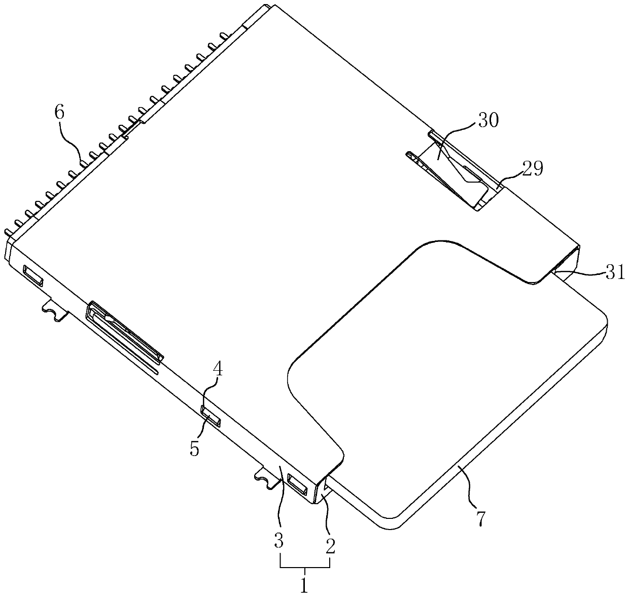
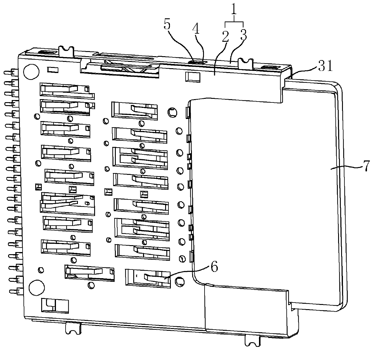
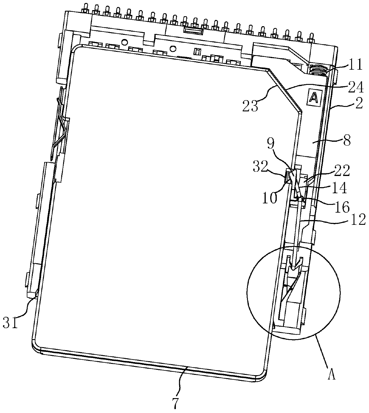
[0035] An SD card holder, such as figure 1 with figure 2 As shown, it includes a main body 1, the main body 1 includes a bottom base 2 and a top shell 3, a buckle groove 4 is provided on the edge of the shell 3, and a buckle groove 4 is provided on the side wall of the base 2 The buckle block 5, the shell 3 realizes the buckle connection through the buckle groove 4 and the buckle block 5 to realize the detachment of the two, and the assembly and disassembly operation is convenient and quick, and the base 2 is provided with a slot 31 for the SD card 7 to be plugged in. An insertion opening is formed on one side, and a plurality of terminal groups 6 for electrical connection are plugged into the base 2. After the SD card 7 is inserted into the slot 31, its metal gasket abuts against the terminal group 6 to realize electrical connection, thereby realizing dat...


PUM


Abstract

The invention discloses an SD card holder, which comprises a body provided with a slot for an SD card to be inserted into. A slide block is connected in a sliding manner in the slot. An elastic clamping block used for being connected with the SD card in a clamping manner is arranged on the sliding block. The slide block is connected with a pull rod. A slide slot for one end of the pull rod to slide is arranged in the slot. A limit slot for the end of the pull rod to be clamped is arranged in the slide slot. One end of the pull rod is rotationally connected to the slide block, and an abutting rod extends from the end. One end of the abutting rod abuts against the side of the elastic clamping block away from the SD card. Because the abutting rod is arranged, the SD card is clamped to the elastic clamping block first after being inserted into the slot, and is then clamped into the limit slot for fixation with the help of the pull rod. At the moment, the abutting rod abuts against the elastic clamping block at one end to stop deformation, and the SD card cannot be pulled out even if the SD card is held by a hand. Thus, the SD card will not be pulled out by mistake, and the insertion ofthe SD card is firmer.

Description

technical field [0001] The invention relates to the field of memory cards, more specifically, it relates to an SD card holder. Background technique [0002] SD card is a memory card standard, which is widely used in portable devices, such as digital cameras and multimedia players and other electronic products. SD cards need to be plugged into SD card holders for data storage. SD cards usually include a main body On one side of the main body, there is a slot for inserting the SD card. There are multiple terminal groups on the main body. The metal pads on the SD card are in contact with the terminal groups on the SD card holder to achieve electrical conduction, and then signal transmission. A slide block is set in the slot, and the slide block is provided with an elastic card block for engaging with the card slot on the SD card holder, so that after the SD card is inserted into the slot, it can be connected with the slide block by means of the card connection of the elastic ca...

Claims


Application Information

Patent Timeline
IPC IPC(8): H01R12/71H01R13/627
CPCH01R12/714H01R13/6278
Inventor 林英成
Owner SHENZHEN BEITEKANG TECH CO LTD
Learn More