Rectifying plate and grooved cleaning machine

A rectifying plate and cleaning machine technology, which is applied to chemical instruments and methods, cleaning methods and appliances, electrical components, etc., can solve the problems that the lower chamber of the tank is difficult to clean, so as to improve the utilization rate of the machine, facilitate cleaning, and save energy. The effect of maintenance time

Inactive Publication Date: 2019-08-20
HUAIAN IMAGING DEVICE MFGR CORP
View PDF12 Cites 0 Cited by
  • Summary
  • Abstract
  • Description
  • Claims
  • Application Information

AI Technical Summary

Problems solved by technology

[0005] The technical solution of the present invention is to solve the technical problem that the lower cavity of the tank body is difficult to clean due to the arrangement of rectifying plates in the existing tank cleaning machine

Method used


Image

  • Rectifying plate and grooved cleaning machine
  • Rectifying plate and grooved cleaning machine
  • Rectifying plate and grooved cleaning machine

Examples


Embodiment Construction

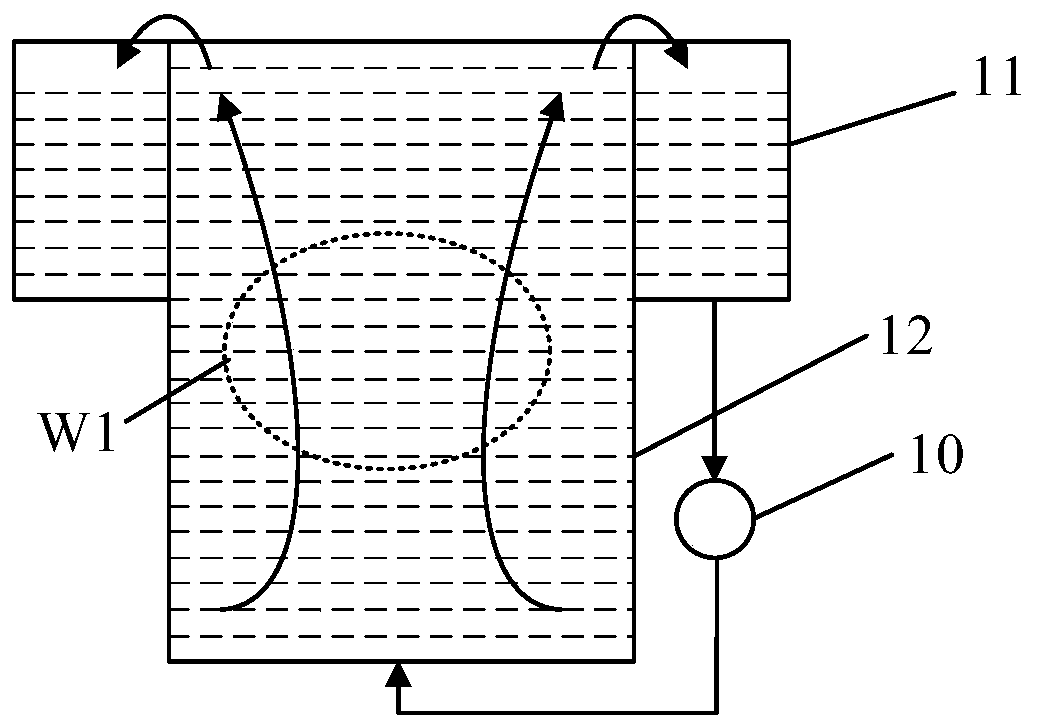
[0031] Such as figure 1 As shown, in a conventional tank cleaning machine, the cleaning liquid is generally circulated between the outer tank 11 and the inner tank 12 by a pump 10 . However, when the cleaning liquid flows in the inner tank, the problem of uneven flow is likely to occur, resulting in poor uniformity of etching and cleaning of the wafer W1.

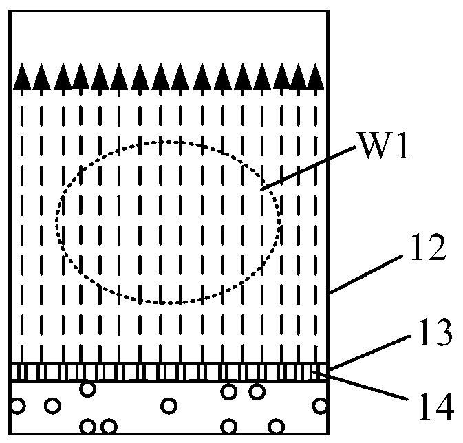
[0032] At present, the way to solve the above-mentioned uneven flow of the cleaning solution is to set a plate-shaped structure with through holes in the inner tank 12, and the wafer W1 is placed on the plate-shaped structure. Such as figure 2 As shown, rectifying plate 13 is set in inner groove 12, and rectifying plate 13 is provided with some through holes 14, and through hole 14 makes the liquid by rectifying plate 13 be shunted into more strands, and the liquid of more strands is to rectifying plate 13 The liquid stored in the upper part has the functions of pushing and stirring, so that the various ions in the inner...


PUM


Abstract

The invention discloses a rectifying plate and a grooved cleaning machine. The rectifying plate is applied to a groove body of the grooved cleaning machine, the groove body is provided with a first inner side wall and a second inner side wall which are opposite, the rectifying plate comprises a plurality of baffles which are arranged between the first inner side wall and the second inner side walland are sequentially arranged, the baffles are provided with a through holes, and the baffles can be rotated to the position parallel to the bottom of the groove body. The rectifying plate has the advantages that the dismantling and installing procedures needed when the groove body is cleaned are eliminated, the maintenance time is reduced, and therefore the using efficiency of a machine is improved.

Description

technical field [0001] The invention relates to the technical field of semiconductor manufacturing, in particular to a rectifying plate and a tank cleaning machine. Background technique [0002] In the semiconductor manufacturing process, the tank cleaning machine is widely used in the fields of wet cleaning and wet etching due to its high throughput. In the tank cleaning machine, the cleaning liquid is generally circulated between the outer tank and the inner tank by means of a pump. However, the liquid in the inner tank is prone to uneven flow when it flows, resulting in poor uniformity of etching and cleaning. [0003] The current solution is to set a rectifying plate in the inner tank, the rectifying plate divides the inner tank into an upper cavity and a lower cavity, and a number of through holes are arranged on the rectifying plate, and the through holes divide the liquid passing through the rectifying plate , so that the liquid passing through the rectifying plate ...

Claims


Application Information

Patent Timeline
Patent Type & Authority Applications(China)
IPC IPC(8): B08B13/00H01L21/67
CPCB08B13/00H01L21/67023H01L21/6704H01L21/67075
Inventor 李丹高英哲张文福刘家桦叶日铨
Owner HUAIAN IMAGING DEVICE MFGR CORP
Why Eureka
Try Eureka