Non-contact type cast ingot laser marking device, work method and analogy method

A laser marking, non-contact technology, applied in the direction of laser welding equipment, welding equipment, manufacturing tools, etc., can solve the problems of vertical focus, automatic positioning and automatic marking, etc.

Inactive Publication Date: 2019-08-20
LANZHOU UNIVERSITY OF TECHNOLOGY
View PDF6 Cites 3 Cited by
  • Summary
  • Abstract
  • Description
  • Claims
  • Application Information

AI Technical Summary

Problems solved by technology

The disadvantages of the traditional automatic laser marking equipment for aluminum ingots are: the functions of vertical focus, automatic positioning and automatic marking cannot be realized

Method used


Image

  • Non-contact type cast ingot laser marking device, work method and analogy method
  • Non-contact type cast ingot laser marking device, work method and analogy method
  • Non-contact type cast ingot laser marking device, work method and analogy method

Examples


Embodiment Construction

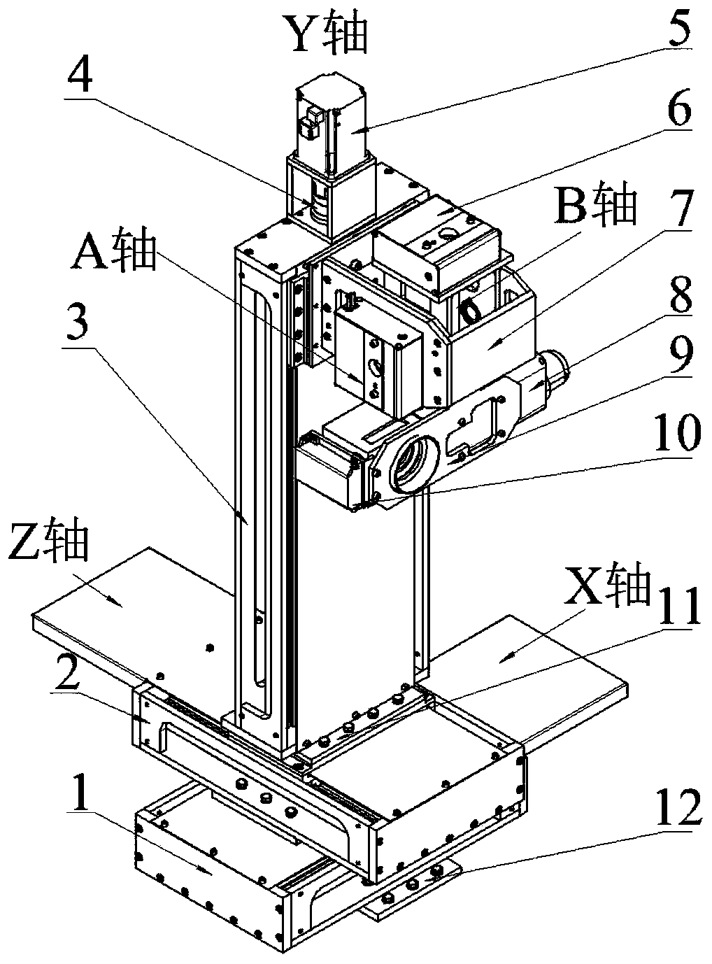
[0020] Such as figure 2 As shown, this non-contact laser marking equipment for casting ingots includes: a three-way feeding system, a linear mechanism, a table 7, a laser marking unit, a three-dimensional line laser scanner 10, and a machine base 12;

[0021] The three-direction feed system includes X-direction feed system, Y-direction feed system, and Z-direction feed system. The linear mechanism includes X-axis actuator 1, Y-axis actuator 3, and Z-axis actuator 2. The corresponding linear mechanism is driven by the system respectively, among which the X-direction feed system, the Z-direction feed system, the X-axis actuator and the Z-axis actuator are on the base of the whole machine, and the Y-direction feed system and the Y-axis actuator are perpendicular to the whole machine. machine base;

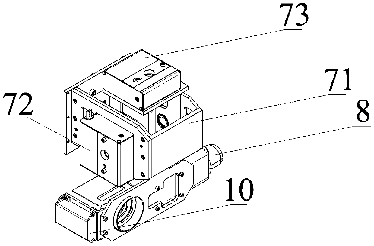
[0022] The swing table is connected with the Y-axis actuator and swings up, down, left, and right. The laser marking unit includes a laser marking head 8 and a laser marking head br...


PUM


Abstract

A non-contact type cast ingot laser marking device comprises a three-directional feed system, linear mechanisms, a swing table (7), a laser marking unit, a three-dimensional line laser scanner (10) and an overall machine base (12). The three-directional feed system comprises an X-direction feed system, a Y-direction feed system and a Z-direction feed system. The linear mechanisms correspondingly comprise an X-axis actuating mechanism (1), a Y-axis actuating mechanism (3) and a Z-axis actuating mechanism (2). The three-way feed system drives the corresponding linear mechanisms. The X-directionfeed system, the Z-direction feed system, the X-axis actuating and the Z-axis actuating mechanism are arranged on the overall machine base, and the Y-direction feed system and the Y-axis actuating mechanism are perpendicular to the overall machine base. The swing table is connected with the Y-axis actuating mechanism and swings in the up-down and left-right directions. The laser marking unit comprises a laser marking head (8) and a laser marking head support (9). The laser marking head is fixed to the swing table by the laser marking head support, and the three-dimensional line laser scanner is fixed to the support. The invention also provides a work method and an analogy method.

Description

technical field [0001] The invention relates to the technical field of mechanical structure design, in particular to a non-contact laser marking equipment for casting ingots, and a working method and a simulation method of the equipment. Background technique [0002] In non-ferrous metal production enterprises, aluminum ingots are the most common. It is designed according to international standards, and its shape fully considers the transportation of aluminum ingots. All aluminum ingots in the stack are interlocking (such as figure 1 shown). When the automatic robot is stacking, the aluminum ingots on the bottom layer of the stack are placed in the same direction to ensure the flatness of the bottom layer, which is convenient for bundling and forklifting. The aluminum ingots are placed at 90° to each other. The position of the marked surface on the aluminum ingot stack is located on the right side of the uppermost layer of the entire aluminum ingot stack. [0003] The mec...

Claims


Application Information

Patent Timeline
Patent Type & Authority Applications(China)
IPC IPC(8): B23K26/362B23K26/70
CPCB23K26/362B23K26/702
Inventor 李建华芮执元辛舟沈浩靳岚杨建军罗德春赵俊天
Owner LANZHOU UNIVERSITY OF TECHNOLOGY
Why Eureka
Try Eureka