Circular-handle cutter rapid clamp

A cutting tool and fast technology, applied in the direction of clamping, manufacturing tools, supports, etc., can solve the problems of low reuse rate, inability to replace fixtures, low clamping efficiency, etc., and achieve large clamping force and high clamping efficiency , Reliable clamping effect

Inactive Publication Date: 2019-08-20
常州国锐工具有限公司
View PDF11 Cites 13 Cited by
  • Summary
  • Abstract
  • Description
  • Claims
  • Application Information

AI Technical Summary

Problems solved by technology

The jig in the prior art round shank tool processing method is based on a square jig, and a hole corresponding to the diameter of the round shank tool to be processed is cut out in the middle, so that when processing round shank tools with different diameters, It is impossible to replace the fixtures with holes of different diameters, which makes the existing round handle tool fixtures more restrictive in the use process, the reuse rate is not high, and the clamping efficiency is low and the clamping is inconvenient

Method used


Image

  • Circular-handle cutter rapid clamp
  • Circular-handle cutter rapid clamp
  • Circular-handle cutter rapid clamp

Examples


Embodiment 1

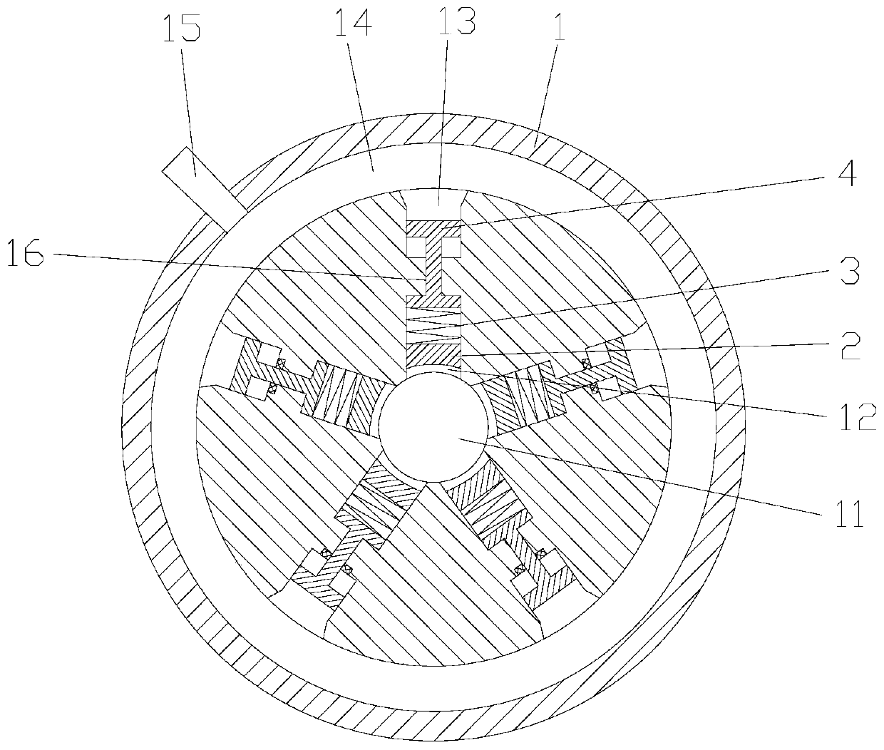
[0024] Example 1: Reference figure 1 , a round shank tool quick clamp, including a cylindrical clamping body 1, five chucks 2, the axis of the clamping body 1 is provided with a clamping hole 11 for placing the round shank tool, and the surrounding of the clamping hole 11 is provided with a clamping hole 11. There are five chutes 12 along the radial direction. The chutes 12 are evenly distributed along the circumferential direction. The front end of the chutes 12 communicates with the clamping hole 11. The line and the axis line of the chute 11 are on the same radial straight line. There is a spring 3 in the air pressure chamber 13, and the ejector rod 4 is slidingly matched with the air pressure chamber 13. The front end of the ejector rod 4 extends to the rear of the spring 3 and is connected with the rear end of the spring 1. The clamping body 1 The rear part corresponding to the air pressure chamber 13 is provided with an annular air pressure chamber 14 which communicates...

Embodiment 2

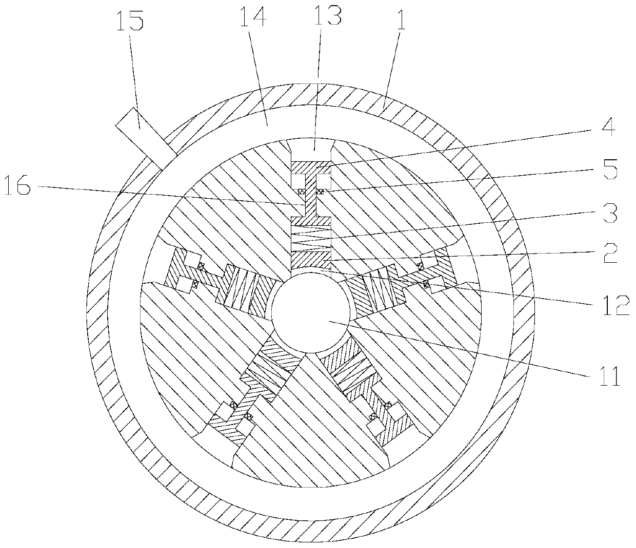
[0026] Embodiment 2: The difference between this embodiment and Embodiment 1 is: refer to figure 2 , the inner wall of the connecting cavity 16 is provided with an axial sealing ring 5 that seals the sliding fit between the inner wall of the connecting cavity and the ejector cylinder. The efficiency is transformed, the air pressure loss is reduced, and the clamping force of the spring on the tool is guaranteed.

Embodiment 3

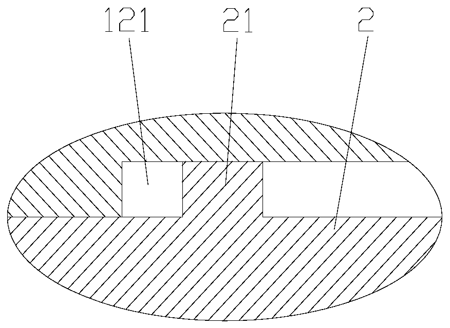
[0027] Embodiment 3: The difference between this embodiment and Embodiment 1 is: refer to image 3 , the groove wall of the sliding groove 132 is provided with a matching groove 121 along the radial direction, and the corresponding position on the collet 2 is provided with a limit block 21 that cooperates with the matching groove 121. The limit block 21 slides in the matching groove 121 to limit the collet The position of radial movement can prevent the collet from slipping out, and make the clamp have a certain scope of application and improve the clamping accuracy.


PUM


Abstract

The invention relates to the technical field of mechanical clamps, in particular to a circular-handle cutter rapid clamp. The circular-handle cutter rapid clamp comprises a clamp body, a plurality ofclamping heads capable of synchronously moving are arranged on the clamp body, a clamping hole for containing a round handle cutter is formed in the middle of the clamp body, a plurality of sliding grooves in the radial direction are formed in the periphery of the clamping hole, the sliding grooves are uniformly distributed in the circumferential direction, the front ends of the sliding grooves are in communication with the clamping hole, air pressure cavities are formed in the rear sides of the sliding grooves, the axes of the air pressure cavities and the axes of the sliding grooves are in the same radial straight line, one ends of the clamping heads are correspondingly arranged in the sliding grooves and is in sliding fit with the sliding grooves, springs are arranged at the rear partsof the clamping heads in the sliding grooves, ejector rods are arranged in the air pressure cavities and are in sliding fit with the air pressure cavities, the front ends of the ejector rods extend tothe rear ends of the springs and are connected with the rear end of the springs, and an annular air pressure chamber communicating with the air pressure cavities is arranged on the clamp body corresponding to the rear parts of the air pressure cavities. The circular-handle cutter rapid clamp is high in clamping efficiency and can be applied to circular-handle cutters with different outer diameters.

Description

technical field [0001] The invention relates to the technical field of mechanical fixtures, in particular to a quick fixture for round shank tools. Background technique [0002] The round shank tool is processed on the machine tool during the production process. It is often necessary to place the cylindrical round bar base material on the fixture and clamp it, and then use methods such as grinding to process the cutting edge. The fixture in the prior art round shank tool processing method is based on a square fixture, and a hole corresponding to the diameter of the round shank tool to be processed is cut out in the middle, so that when processing round shank tools of different diameters, It is impossible to replace the clamps with holes of different diameters, so that the existing round shank tool clamps are more restrictive in the use process, and the repeated utilization rate is not high, and the clamping efficiency is low and the clamping is inconvenient. SUMMARY OF THE...

Claims


Application Information

Patent Timeline
Patent Type & Authority Applications(China)
IPC IPC(8): B23Q3/00
CPCB23Q3/00
Inventor 李春波
Owner 常州国锐工具有限公司
Why Eureka
Try Eureka