Assistance mechanical arm structure based on truss robot

A technology of a truss robot and a mechanical arm, applied in the field of truss robots, can solve problems such as the inability of the Z-axis arm to bypass and operate, and achieve the effect of improving practicability, applicability and flexibility

Inactive Publication Date: 2019-08-20
HUBEI HAILIAN TECH CONSULTATION CO LTD
View PDF1 Cites 0 Cited by
  • Summary
  • Abstract
  • Description
  • Claims
  • Application Information

AI Technical Summary

Problems solved by technology

[0006] In order to solve the above technical problems, the present invention provides a power-assisted mechanical arm structure based on a truss robot to solve the problem that when the X

Method used


Image

  • Assistance mechanical arm structure based on truss robot
  • Assistance mechanical arm structure based on truss robot
  • Assistance mechanical arm structure based on truss robot

Examples


Embodiment

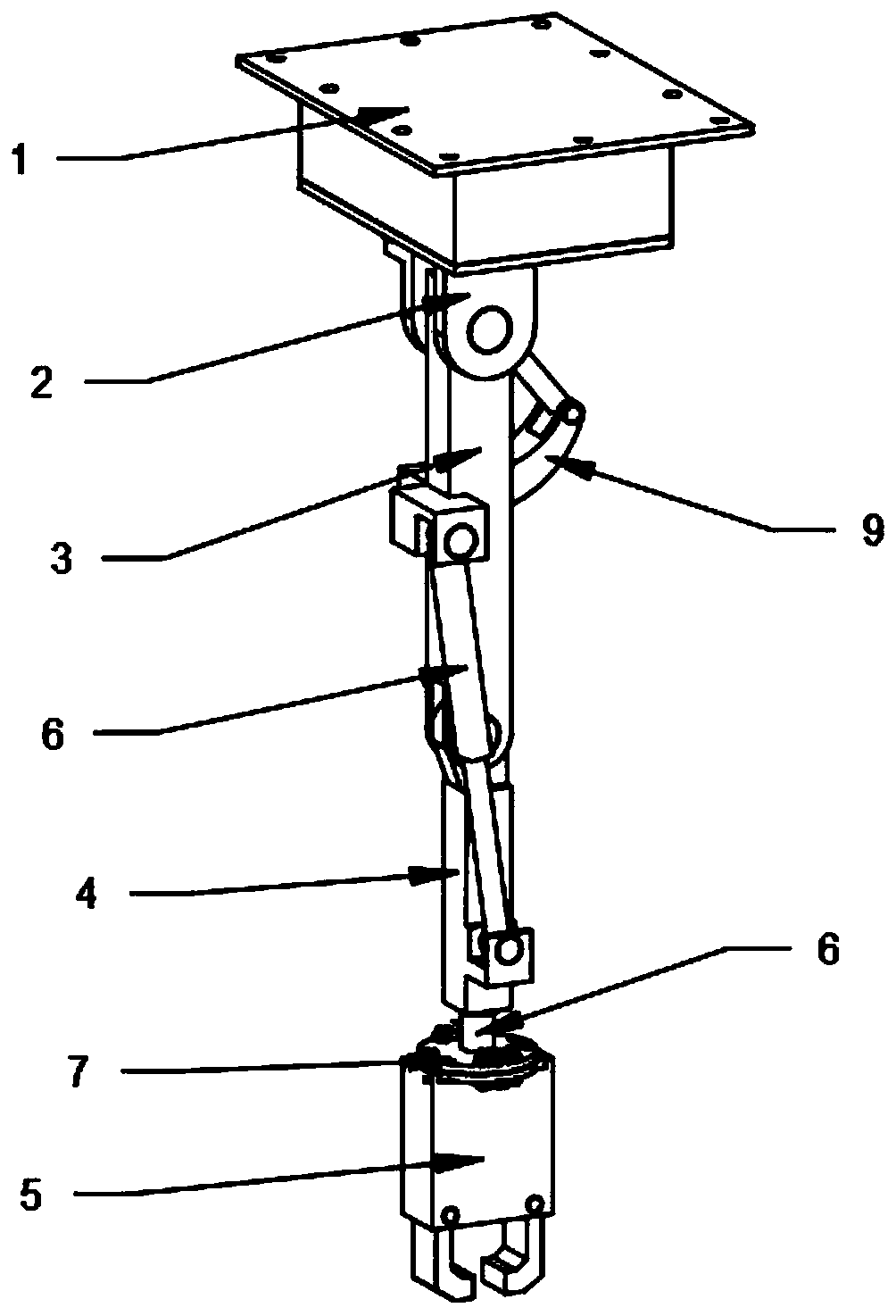
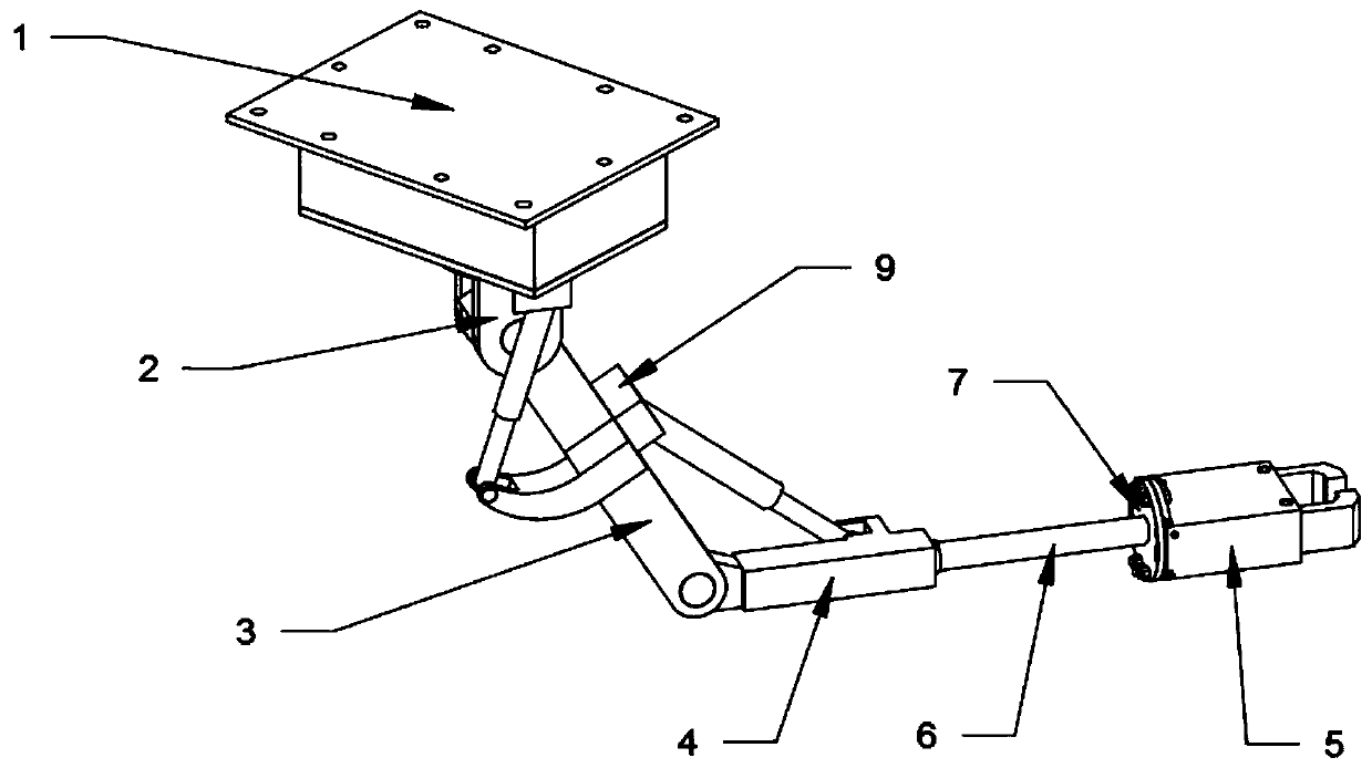
[0026] as attached figure 1 to attach Figure 4 Shown:

[0027] The present invention provides a power-assisted mechanical arm structure based on a truss robot, including a connecting seat 1, a turntable 2, a longitudinal arm 3, a cross arm 4, a gripper device 5, an electric push rod 6, a connecting plate 7, a reduction motor 8 and a connecting block 9. The inside of the connection seat 1 is provided with a rectangular installation body, and the installation body is provided with a motor installation slot and a turntable 2 installation slot, and the connection seat 1 is screwed to the Z-axis arm of the truss robot through the reserved screw hole on the top. One end of the turntable 2; the turntable 2 is fixedly connected in the installation groove of the turntable 2 inside the connecting seat 1, and a square connecting block 9 is provided on one side of the turntable 2; the longitudinal arm 3 is movably connected to the top of the turntable 2 through a connecting rod In the ...


PUM


Abstract

The invention provides an assistance mechanical arm structure based on a truss robot. The assistance mechanical arm structure comprises a longitudinal arm, a transverse arm and an electric push rod. The longitudinal arm is movably connected in a connecting hole in the top of a rotating table through a connecting rod. The transverse arm is movably connected to one end of the longitudinal arm, and the length-through electric push rod is arranged in the transverse arm. A square connecting block is arranged on the side face of one end of the transverse arm. Due to the cooperation effect of the rotating table, the electric push rod and various levels of arm rods, a Z-axis arm can bend, rotate, stretch and contract, when blocking happens to the XY plane of the top of a working position, the structure can change the shape flexibly and wind around an obstacle to work normally at the bottom work position, the problem that when blocking of a solid object exists on the XY plane of the top of thework position of an existing truss robot, the Z-axis arm cannot wind wound the solid object of the XY plane is solved, and practicability and adaptability of the device are improved.

Description

technical field [0001] The invention belongs to the technical field of truss robots, and more specifically relates to a structure of a power-assisted mechanical arm based on a truss robot. Background technique [0002] The truss robot is also called a Cartesian robot. It uses the XYZ Cartesian coordinate system as the basic mathematical model, and the single-axis mechanical arm driven by the servo motor and stepping motor as the basic working unit. The robot system constructed by the commonly used transmission method can complete the arrival at any point in the XYZ three-dimensional coordinate system and follow the controllable motion trajectory. [0003] For example, in the patent with the application number: CN201721603204.X, a truss robot Z-axis combined grasping mechanism is disclosed, including the Z-axis and the tooling main board arranged at the lower end of the Z-axis; the lower end of the Z-axis is provided with a cylinder clamp Holding mechanism one; the cylinder ...

Claims


Application Information

Patent Timeline
IPC IPC(8): B25J9/02B25J15/02B25J15/08B25J18/02
CPCB25J9/023B25J15/0253B25J15/08B25J18/025
Inventor 朱献忠徐祖建苏平王鹏
Owner HUBEI HAILIAN TECH CONSULTATION CO LTD
Why Eureka
Try Eureka