
Knob-type yarn tension regulator

A yarn tension and tension adjustment technology, which is applied in the direction of conveying filamentous materials, thin material processing, transportation and packaging, etc. It can solve the problems of large loss of iron wire and iron hook, troublesome and time-consuming adjustment, and narrow adaptation surface of tensioner, etc. Problems, to achieve the effect of improving production efficiency, large yarn thickness span, and reducing adjustment time

Active Publication Date: 2019-08-20
TIANHAI LACE CO LTD
View PDF21 Cites 1 Cited by
  • Summary
  • Abstract
  • Description
  • Claims
  • Application Information

AI Technical Summary

Problems solved by technology

[0008] The technical problem mainly solved by the present invention is to provide a knob-type yarn tension regulator to solve the above-mentioned problems in the use of the tensioner in the prior art: different tensioners should be used when the tensioner has a narrow adaptable surface and a large difference in thickness ;The iron wire and iron hook for adjusting the tension have a large loss, and the iron wire and iron hook are easy to fall from the tensioner; it is troublesome and time-consuming to adjust the tension; Falling into the machine and causing accidental damage to the machine

Method used


Image

  • Knob-type yarn tension regulator
  • Knob-type yarn tension regulator
  • Knob-type yarn tension regulator

Examples


Embodiment Construction

[0026] The present invention will be described in detail below in conjunction with the accompanying drawings and embodiments.

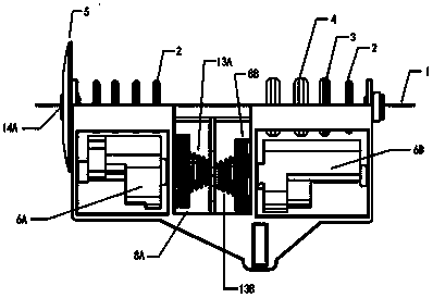
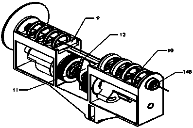
[0027] Such as figure 1 As shown, a tension disc 5 is set at the yarn entrance. The function of the tension disc 5 is to straighten the yarn before the yarn 1 enters the knob-type yarn tension regulator, so as to prevent the yarn 1 from catching the knob-type yarn tension regulator when twisted. Parts of the yarn tension regulator cause the problem of yarn tightness; yarn 1 enters the knob-type yarn tension regulator from the magnetic eye 14A in the middle of the tension disc 5, and then passes through the first set of tension pressure rings. The pressure ring is composed of 4 tension pressure rings 2 2 with the same weight. Whether these 4 tension pressure rings 2 have a positive pressure effect on the yarn 1 depends on the position of the corresponding cam upper edge of the cam group 6A; the yarn 1 wears After passing through the first group of ten...


PUM


Abstract

The present invention discloses a knob-type yarn tension regulator, comprising: a stand, a tension regulating knob, a cam group, a piercing rod, a tension rod, tensioning rings, a yarn inlet and a yarn outlet; the knob-type yarn tension regulator regulates the tension of a single yarn, the yarn firstly enters the knob-type yarn tension regulator from a magnetic hole at the middle of a tension plate of the yarn inlet, then passes through the first group of tensioning rings and the second group of tensioning rings, finally gets out from a magnetic hole of the yarn outlet; the cam group is drivento rotate by turning the tension regulating knob, thus realizing selection of different tensioning rings and achieving the goal of applying different specific tensions to yarns.

Description

technical field [0001] The invention relates to the field of textile machinery, in particular to a yarn tension regulating device. Background technique [0002] The control of yarn tension is particularly important in textile enterprises. The level of yarn tension control directly determines the grade and quality of the products produced. [0003] In order to better control the yarn tension, the production enterprise makes the regular yarn into a pan head or flower shaft, and uses the active warp let-off method to achieve uniform yarn supply and controllable tension fluctuation, thereby improving product quality. However, this control method is very limited, especially for warp knitting jacquard products with very poor regularity, the yarn supply of fancy yarn can hardly be realized by pan head or flower shaft (the demand for yarn between bars is very different). Large, instantaneous yarn consumption changes greatly), can not achieve good tension control, and the cost is hi...

Claims


Application Information

Patent Timeline
Patent Type & Authority Applications(China)
IPC IPC(8): B65H59/10
CPCB65H59/10
Inventor 沈宁一曾宪忠许术超
Owner TIANHAI LACE CO LTD
Learn More