Magnetron sputtering coating device

A magnetron sputtering coating and equipment technology, applied in the field of magnetron sputtering, can solve the problems of the reduction of high-energy electrons bombarding the substrate, the difficulty of ensuring uniformity and consistency, etc., to achieve expanded utilization efficiency, ideal structure, and reduce investment cost effect

Active Publication Date: 2019-08-20
河南东微电子材料有限公司
View PDF7 Cites 2 Cited by
  • Summary
  • Abstract
  • Description
  • Claims
  • Application Information

AI Technical Summary

Problems solved by technology

Magnetron sputtering coating is a technology that uses energetic particles to bombard the target surface in vacuum, so that the bombarded particles are deposited on the substrate. It is to add a magnetic field in the sputtering environment, and use the Lorentz force of the magnetic field to bind the surface of the cathode target. The movement of electrons leads to the increase of high-energy ions bombarding the target and the decrease of high-energ

Method used


Image

  • Magnetron sputtering coating device
  • Magnetron sputtering coating device
  • Magnetron sputtering coating device

Examples


Embodiment 1

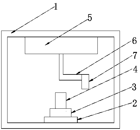
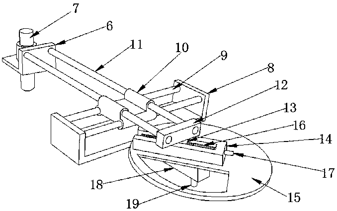
[0022] Embodiment one, such as Figure 1-3 As shown, a magnetron sputtering coating device according to an embodiment of the present invention includes a vacuum chamber 1, a substrate stage 2 is provided at the inner lower end of the vacuum chamber 1, and a target holder is provided at the upper end of the substrate stage 2. 3. The upper end of the target base 3 is provided with a fixing device 4, the inner upper end of the vacuum chamber 1 is provided with a rotating device 5, the lower end of the rotating device 5 is provided with a connecting piece 6, and one end of the connecting piece 6 is provided There is a magnetron target 7, wherein the rotating device 5 includes a fixed frame 8, and the upper end of the fixed frame 8 is connected to the inner upper end of the vacuum chamber 1, and two groups of The fixed rod 9 is provided with a slide plate 10 on the fixed rod 9, and two sets of movable rods 11 are interspersed on both sides of the top of the slide plate 10, and one ...

Embodiment 2

[0023] Embodiment two, such as figure 2 As shown, and, the slide plate 10 has a double-layer structure, two sets of fixed rods 9 penetrate the lower end of the slide plate 10, two sets of movable rods 11 penetrate the upper end of the slide plate 10, and the The fixed rod 9 and the movable rod 11 are perpendicular to each other.

Embodiment 3

[0024] Embodiment three, such as figure 2 As shown, the joints of the screw mandrel 16, the slider 13 and the chute 14 are provided with internal threads matched with the screw mandrel 16, and the lower end of the movable plate 15 is connected to the fixed frame. 8 are fixedly connected by a support frame 18, and a movable shaft 19 is provided at the bottom of the lower end of the movable disk 15, and a drive motor is connected to the lower end of the movable disk 19.


PUM


Abstract

The invention discloses a magnetron sputtering coating device. The magnetron sputtering coating device comprises a vacuum chamber, a substrate table is arranged at the lower end of the interior of thevacuum chamber, a target seat is arranged at the upper end of the substrate table, a fixing device is arranged at the upper end of the target seat, a rotating device is arranged at the upper end of the interior of the vacuum chamber, a connecting piece is arranged at the lower end of the rotating device, a magnetic control target is arranged at one end of the connecting piece, the rotating devicecomprises a fixing frame, the upper end of the fixing frame is connected with the upper end of the interior of the vacuum chamber, two sets of fixing rods are arranged between the upper ends of the fixing frame, sliding plates are arranged on the fixing rods in a sleeved mode, two groups of movable rods are arranged on the two sides of the top of the sliding plates in a penetrating mode, one endsof the two groups of movable rods are fixedly connected with one side of the connecting piece, a movable block is arranged at one end, far away from the connecting piece, of the two groups of movablerods, a sliding block is arranged at the lower end of the movable block, the sliding block is located on the inner side of a sliding chute, the sliding block is matched with the sliding chute, the sliding chute is positioned at the upper end of a movable disc, on one side of the lower end of the movable disc and is connected with the fixed frame; a screw rod matched with the slide block is arranged in the slide block in a penetrating manner.

Description

technical field [0001] The invention relates to the technical field of magnetron sputtering, in particular to a magnetron sputtering coating equipment. Background technique [0002] At present, magnetron sputtering technology is a surface modification technology that has been widely used in experiments and production in the fields of physical science and material science. Magnetron sputtering coating is a technology that uses energetic particles to bombard the target surface in vacuum, so that the bombarded particles are deposited on the substrate. It is to add a magnetic field in the sputtering environment, and use the Lorentz force of the magnetic field to bind the surface of the cathode target. The movement of electrons leads to the increase of high-energy ions bombarding the target and the decrease of high-energy electrons bombarding the substrate, which makes the coating process have the characteristics of low temperature and high speed. Among the magnetron sputtering c...

Claims


Application Information

Patent Timeline
IPC IPC(8): C23C14/35C23C14/50
CPCC23C14/3407C23C14/35C23C14/50
Inventor 王伟涛王永超杨玉杰李建勋付宪坡张军营
Owner 河南东微电子材料有限公司
Why Eureka
Try Eureka