
Lens main section calibration device

A technology of calibration device and main section, applied in the direction of testing optical performance, etc., can solve the problems of repeated calibration, poor main section accuracy, inconvenient prism, etc., and achieve the effect of improving work accuracy and reliability, avoiding errors, and avoiding delay errors.

Active Publication Date: 2019-08-20
TONGJI UNIV
View PDF5 Cites 0 Cited by
  • Summary
  • Abstract
  • Description
  • Claims
  • Application Information

AI Technical Summary

Problems solved by technology

At present, the calibration of the main section of the prism is to mark the main section before the prism is processed, and process the prism with the main section marked as the reference. For the prism that has not calibrated the main section during processing, the existing technology is to refract the light source beam through the prism and seek the deflection of the prism. The maximum position of the beam is used to determine the main section of the prism. The accuracy of the main section determined by this method is poor, and the prism needs to be calibrated repeatedly, which brings great inconvenience to the practical application of the prism.

Method used


Image

  • Lens main section calibration device
  • Lens main section calibration device
  • Lens main section calibration device

Examples


Embodiment

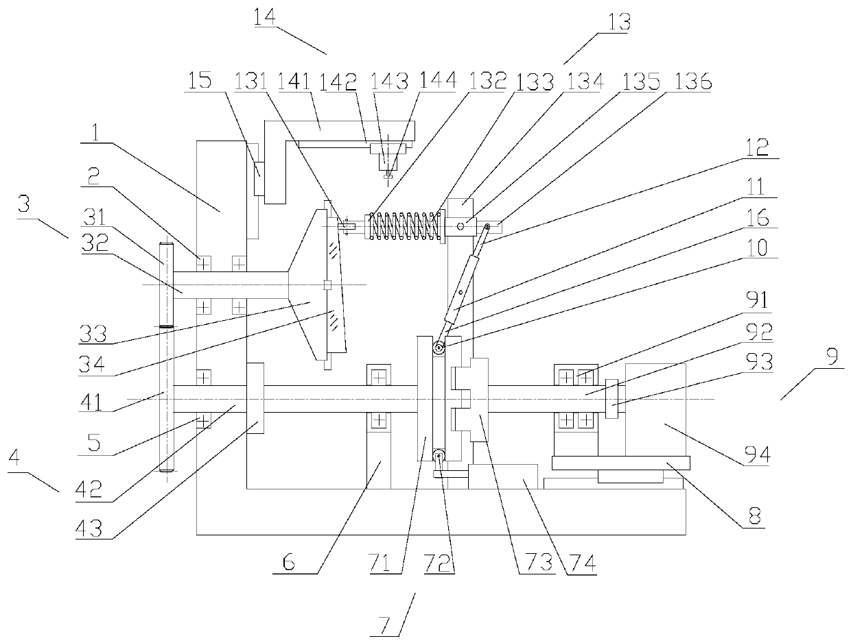
[0044] A lens main section calibration device, including a base 1 and a rotating mirror assembly 3 installed on the base 1, a transmission assembly 4, a clutch assembly 7, a power source assembly 9, a measurement assembly 13 and a marking assembly 14; figure 1 shown. The base 1 is an L-shaped base, including a side surface and a bottom surface. The mirror body 34 to be tested is installed on the rotating mirror assembly 3; the power source assembly 9 drives the rotating mirror assembly 3 to rotate through the clutch assembly 7 and the transmission assembly 4.

[0045] Measuring assembly 13 comprises pressure roller 131, nut 132, spring 133, column 134, slide seat 135 and guide rod 136; Column 134 is vertically fixed on the bottom surface of base 1, and slide seat 135 is flexibly connected to the top of column 134, guide The rod 136 runs through the sliding seat 135 and is slidingly connected with the sliding seat 135; one end of the guide rod 136 is rotationally connected with t...


PUM


Abstract

The invention relates to a lens main section calibration device. The device comprises a base, and a rotary mirror assembly, a transmission assembly, a clutch assembly, a power source assembly and a measuring assembly arranged on the base; a lens body to be tested is mounted on the rotary mirror assembly; the power source assembly drives the rotary mirror assembly to rotate through the clutch assembly and the transmission assembly; the thicknesses of different positions of the lens body are measured through the measuring assembly; under the action of the lens body, the clutch assembly is drivento be opened or closed through a pressing wheel, a guide rod and a roller; and when the clutch assembly is opened, an electromagnetic brake arranged on the transmission assembly prevents the transmission assembly from rotating so as to determine a main section position of the lens body. Compared with the prior art, the device can be applied to the calibration of various types of mirrors such as prisms, concave mirrors and the like, and has the advantages of being wide in application range, convenient in marking, high in precision, high in reliability and the like.

Description

technical field [0001] The invention relates to the field of optical transmission systems, in particular to a lens main section calibration device. Background technique [0002] With the continuous development of space optical systems in imaging and reconnaissance, the use of optical lenses is becoming more and more extensive. Especially for beam scanning and tracking, lenses such as wedge prisms and concave mirrors are widely used. Before the lens is applied, the main section of the lens needs to be calibrated, and the calibration accuracy of the main section of the mirror will directly affect the working accuracy of the optical system. At present, the calibration of the main section of the prism is to mark the main section before the prism is processed, and process the prism with the main section marked as the reference. For the prism that has not calibrated the main section during processing, the existing technology is to refract the light source beam through the prism an...

Claims


Application Information

Patent Timeline
Patent Type & Authority Applications(China)
IPC IPC(8): G01M11/02
CPCG01M11/02
Inventor 李安虎邓兆军
Owner TONGJI UNIV
Learn More