
Outdoor mobile robot charging system and charging method

A mobile robot and charging system technology, which is applied in the field of mobile robots, can solve the problems of large robot load, reduced power, and less converted electric energy, and achieve the effects of improving work efficiency, reducing load, and extending service life

Pending Publication Date: 2019-08-20
SHANDONG IND TECH RES INST OF ZHEJIANG UNIV +2
View PDF0 Cites 0 Cited by
  • Summary
  • Abstract
  • Description
  • Claims
  • Application Information

AI Technical Summary

Problems solved by technology

[0006] The traditional mode of using solar panels for power supply is to place the solar panels on the robot itself, and the solar panels move with the movement of the robot, but there are many disadvantages in this mode: First, to place the solar panels reasonably, the robot The structure needs to be adjusted to adapt to the placement of solar panels, which is not conducive to the large-scale application of solar panels; the second is to limit the number of solar panels placed, too many solar panels, and the robot load is too large, which will inevitably affect The operation of the robot will also affect the service life of the robot. If the number of placement is too small, although the load of the robot is reduced, the stored power is greatly reduced; third, during the movement of the robot, the angle of the solar panel is fixed, so it cannot get enough electricity. Light energy converts less electrical energy; fourth, the illumination of the solar panel depends on the robot. Once the robot works in an environment without light, or stops working and needs maintenance, the solar panel cannot play its role

Method used


Image

  • Outdoor mobile robot charging system and charging method
  • Outdoor mobile robot charging system and charging method
  • Outdoor mobile robot charging system and charging method

Examples


Embodiment 2

[0057] The difference between this embodiment and implementation 1 is: as Figure 5 As shown, the lower charging fork 502 is arranged along the movement path 8 . The advantage of arranging the charging lower fork 502 along the motion path 8 is that since the robot moves along the specific motion path 8, when the robot needs to be charged, it can be charged at any time without shifting the track. Specifically, at least one of the alternating current charging lower fork 5021 and the solar charging lower fork 5022 is provided. In order to ensure sufficient power, multiple power batteries 402 are generally installed on the robot. Multiple power batteries 402 increase the load of the robot virtually, which will affect the operation and service life of the robot. Multiple charging lower forks 502 are set to facilitate the robot Charge at any time to reduce the load on the robot and prolong its service life.

[0058] As a specific implementation, the charging lower fork 502 include...

Embodiment 1

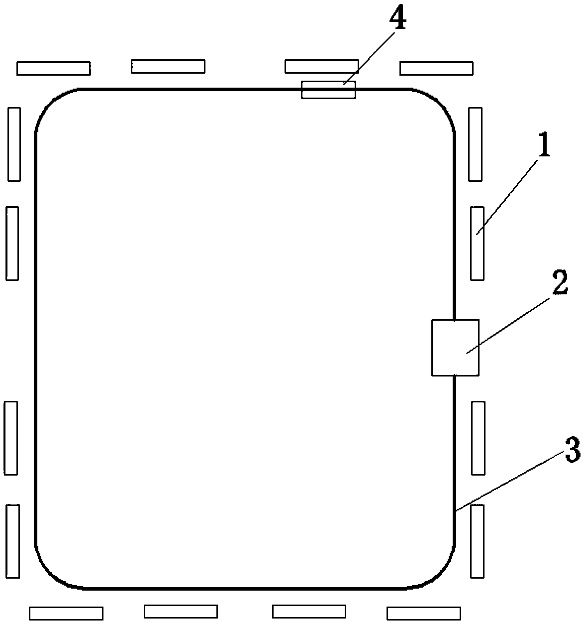
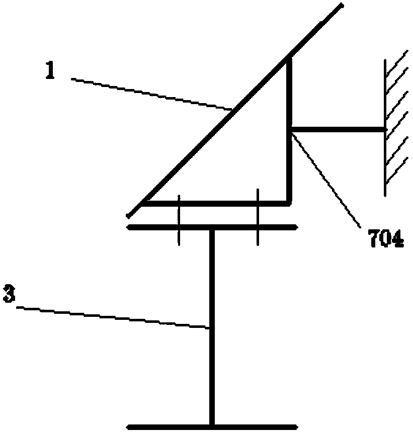
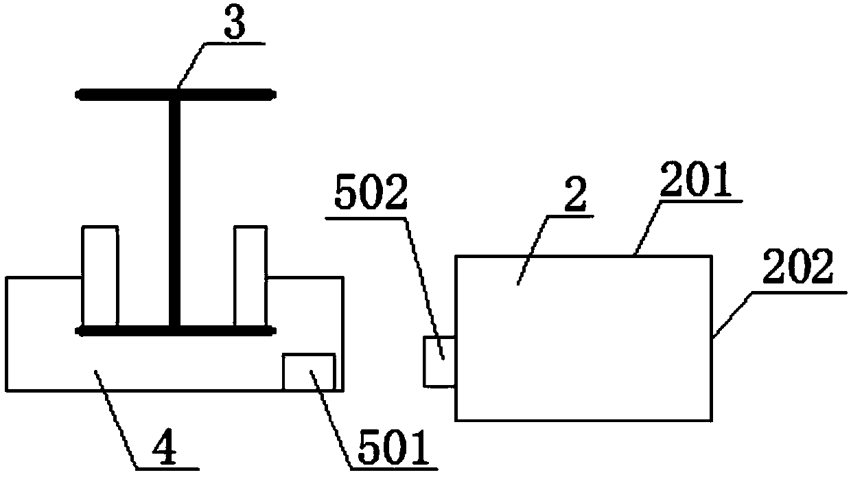
[0064] Such as Figure 1-4 As shown, a charging system for an outdoor track-type mobile robot includes a track 3 on which the robot operates, a power supply device and a charging device 5, the power supply device includes an AC power supply module 6 and a solar power supply module 7, and the charging device includes a charging device arranged on the robot. The fork 501 , and the charging lower fork 502 combined with the charging upper fork 501 , wherein the solar power supply module 7 includes a plurality of solar panels 1 installed on the track 3 . The robot 4 runs along the track 3 and can perform patrol inspection or specific operations. The alternating current is 220V alternating current. Setting the solar panel 1 in the form of distribution along the track 3 has many advantages. First, the solar panel 1 does not need to be fixed on the robot, and the structure of the robot does not need to be adjusted to adapt to the solar panel 1. Robots of any structure or type can be ...


PUM


Abstract

The invention discloses an outdoor mobile robot charging system and charging method. The system comprises a movement path of a robot, a power supply device and a charging device. The power supply device comprises an alternating current power supply module and a solar power supply module, the charging device comprises a charging upper fork portion arranged on the robot and a charging lower fork portion combined with the charging upper fork portion, and the charging lower fork portion is arranged along the movement path. The system has simultaneously has the solar power supply module and the alternating current power supply module, the system can be automatically switched to alternating current for charging when the solar energy is insufficient, two power supplies can be automatically switched, the work of the robot is not affected, the solar energy can be used as an energy of the robot, the system is energy-saving and environment-friendly, the multiple solar panels are intensively arranged along one side of the movement path, enough power can be obtained by conversion, the load of the robot is reduced, and the service life of the robot is prolonged.

Description

technical field [0001] The invention relates to the field of mobile robots, more specifically, it relates to a charging system and a charging method for an outdoor mobile robot. Background technique [0002] The following background art is provided to help the reader understand the present invention and is not to be admitted as prior art. [0003] Outdoor mobile robots integrate many high-tech technologies. It is an inevitable trend in the development of robotics and intelligent inspection technology to use mobile robots to replace manual inspections or operations. The outdoor mobile robot moves on the ground for inspection and has a specific motion path, and the robot travels along the motion path. [0004] When outdoor robots are working, they generally use built-in batteries for power supply. However, when the robot runs for a long time, it needs to be recharged frequently. At present, AC power is often used for recharging. [0005] Solar energy is a clean and renewable...

Claims


Application Information

Patent Timeline
Patent Type & Authority Applications(China)
IPC IPC(8): H02J7/02H02J7/35
CPCH02J7/02H02J7/35
Inventor 孙昊马孝林刘永成王明瑞
Owner SHANDONG IND TECH RES INST OF ZHEJIANG UNIV
Learn More