Scanning data compression method and device, acquisition system and medical imaging system
A technology of scanning data and compression method, applied in the field of data processing, can solve the problems of low data transmission efficiency of CT system, high system cost, CT scanning data compression, etc., and achieve the effect of reducing bandwidth, improving transmission efficiency, and reducing cost
- Summary
- Abstract
- Description
- Claims
- Application Information
AI Technical Summary
Problems solved by technology
Method used
Image

Examples
Embodiment 1
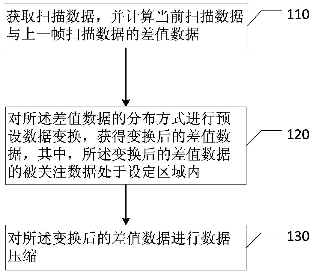
[0028] figure 1 It is a flowchart of a scan data compression method provided by Embodiment 1 of the present invention. This embodiment is applicable to the case of scan data compression. The method can be executed by a scan data compression device, and specifically includes the following steps:
[0029] Step 110, acquire the scan data, and calculate the difference data between the current scan data and the previous frame scan data.
[0030] Wherein, the scan data is data used for imaging, and is generally digital data. It can be the data collected by the detector, or the logarithmically compressed data collected by the detector, also called raw data. The scan data may be logarithmically compressed raw data in the CT imaging system.
[0031] Optionally, the difference data between the current scan data and the previous frame scan data includes:
[0032] Determine whether the current data is the first frame data;
[0033] If so, transfer the current data to the buffer;
[0...
Embodiment 2
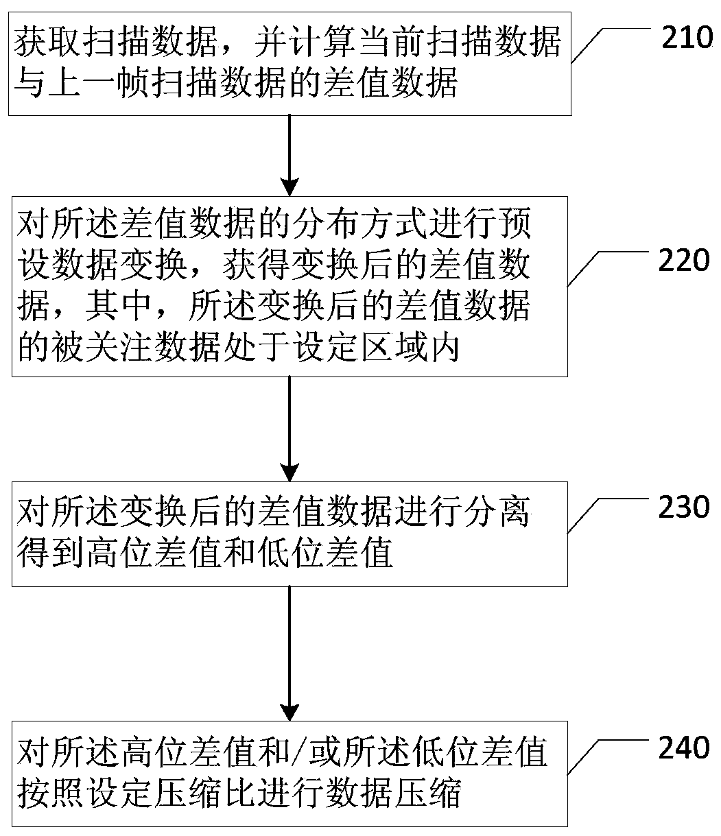
[0062] figure 2 It is a flowchart of a scanning data compression method provided by Embodiment 2 of the present invention. The technical solution of this embodiment is further refined on the basis of the above technical solution. Optionally, as figure 2 As shown, the scanning data compression method provided by the embodiment of the present invention includes:
[0063] Step 210, acquire the scan data, and calculate the difference data between the current scan data and the previous frame scan data.
[0064] Step 220: Perform preset data transformation on the distribution mode of the difference data to obtain transformed difference data, wherein the data of interest in the transformed difference data is within a set area.
[0065] Step 230 , separating the transformed difference data to obtain a high level difference value and a low level difference value.
[0066] Exemplarily, suppose the transformed difference data F i The number of digits is N A , by separating, the F ...
Embodiment 3
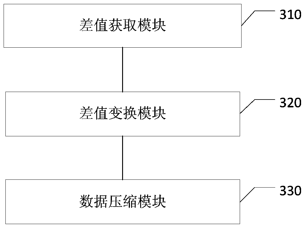
[0100] image 3 It is a schematic structural diagram of a scanning data compression device in Embodiment 3 of the present invention, such as image 3 As shown, the scanning data compression device includes: a difference acquisition module 310 , a difference transformation module 320 and a data compression module 330 .
[0101] Among them, the difference acquisition module 310 is used to acquire the scan data, and calculate the difference between the current scan data and the last frame of scan data; the difference conversion module 320 is used to perform preset conversion on the difference data to obtain Difference data with a distribution rule; wherein, the distribution rule is within a set area of the concerned data set of the difference data; the data compression module 330 is configured to perform data compression on the transformed difference data.
[0102] The technical solution of the embodiment of the present invention solves the problem of data compression of the s...
PUM
 Abstract
Description
Claims
Application Information
 - R&D Engineer
- R&D Manager
- IP Professional
- Industry Leading Data Capabilities
- Powerful AI technology
- Patent DNA Extraction
Browse by: Latest US Patents, China's latest patents, Technical Efficacy Thesaurus, Application Domain, Technology Topic.
© 2024 PatSnap. All rights reserved.Legal|Privacy policy|Modern Slavery Act Transparency Statement|Sitemap