An improved structure of gardening shears

An improved structure and technology of gardening shears, applied in the field of agriculture and gardens, can solve the problems of low work efficiency, inability to cut, inconvenient operation, etc., and achieve the effect of convenient operation

Active Publication Date: 2021-02-26
ZHEJIANG OCEAN UNIV
View PDF5 Cites 0 Cited by
  • Summary
  • Abstract
  • Description
  • Claims
  • Application Information

AI Technical Summary

Problems solved by technology

[0002] In the process of using gardening shears, the distance between the gardening shears and the shearing object is generally judged by visual observation, so there will be problems that the shearing object cannot be cut because the shearing object just exceeds the cutting range of the gardening shears
At this time, other tools are usually used to bring the cut object closer to the cutting range of the gardening shears, and during the cutting process, the cut object needs to be controlled all the time, resulting in inconvenient operation
[0003] In addition, when cutting some scattered branches and leaves, due to the limited working range of the gardening shears, multiple cuttings are required, resulting in low work efficiency.

Method used


Image

  • An improved structure of gardening shears
  • An improved structure of gardening shears
  • An improved structure of gardening shears

Examples


Embodiment 1

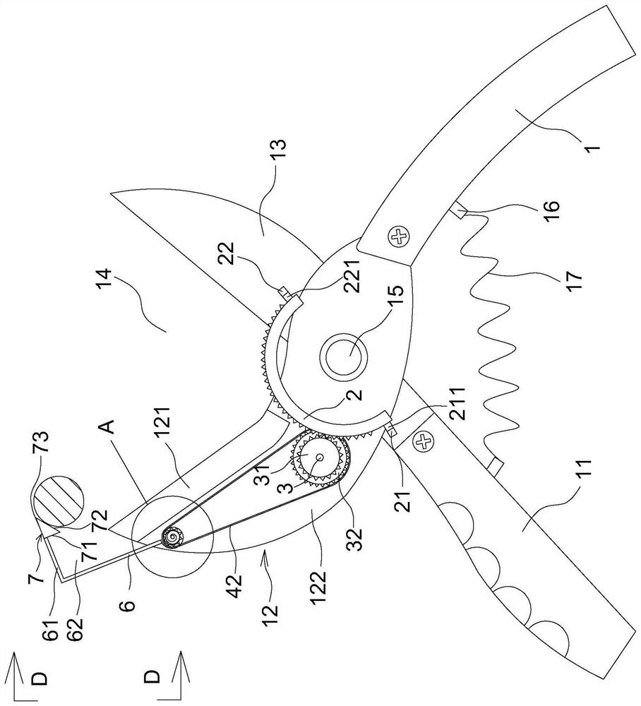
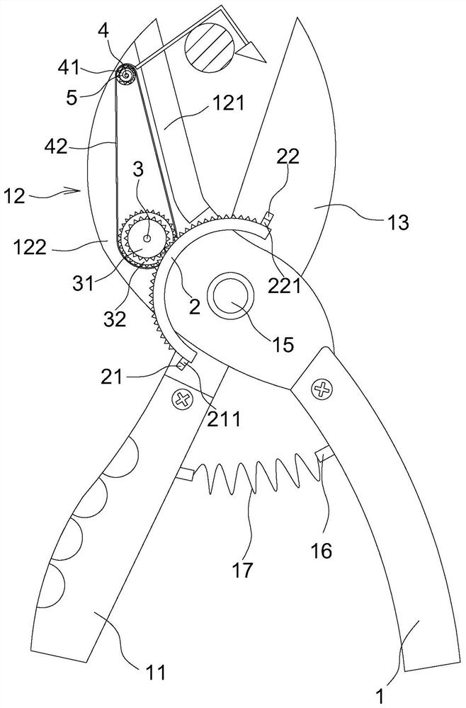
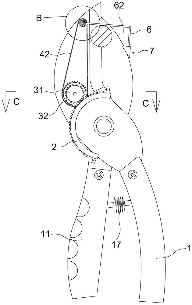
[0032]Refer toFigure 1 to Figure 7, A garden shear with an improved structure, comprising a first blade 12 and a second blade 13 that are crossed and hinged by a hinge shaft 15. The first blade 12 is located above the second blade 13, and the lower end of the first blade 12 is fixed. A first grip 1 is connected, and a second grip 11 disposed opposite to the first grip 1 is fixedly connected to the lower end of the second blade 13 and further includes:

[0033]The first shaft 3 is rotatably arranged on the outer surface of the first blade 12 and is located near the hinge shaft 15. A first blade 12 is provided between the first shaft 3 and the hinge shaft 15 And a driving mechanism for driving the first rotating shaft 3 to rotate when the second blade 13 rotates around the hinge shaft 15;

[0034]The second rotating shaft 4, the second rotating shaft 4 is rotatably arranged on the outer surface of the first blade 12 and located between the tip of the first blade 12 and the first rotating sh...

Embodiment 2

[0059]This embodiment is basically the same as the solution of the first embodiment, but the difference lies in:

[0060]Refer toFigure 8 The return spring 17 and the two spring connecting blocks 16 are replaced with a hydraulic rod 18. The end of the piston cylinder of the hydraulic rod 18 is hinged on the first grip 1, and the end of the piston rod is hinged on the second grip 11. Above, the first grip 1 is provided with a controller 8 and a battery 9, and the controller 8 is electrically connected to the hydraulic rod 18 through the battery 9.

[0061]When working, the hydraulic lever 18 is activated, and the hydraulic lever 18 will drive the first grip 1 and the second grip 11 to move, thereby driving the first blade 12 and the second blade 13 to move, thereby realizing the first rod 6 and the second rod 61 The shearing object is driven to move into the shearing gap 14. This structure facilitates the operation of the first grip 1 and the second grip 11.


PUM


Abstract

The invention belongs to the technical field of agriculture and gardening, and relates to garden shears with an improved structure. The invention comprises a first blade and a second blade hinged by a hinge shaft, a first handle and a second handle are respectively arranged on the first blade and the second blade, and a first rotating shaft and a second rotating shaft are arranged on the first blade A driving mechanism capable of driving the first rotating shaft to rotate when the first blade and the second blade rotate around the hinge shaft is provided between the first rotating shaft and the hinge shaft, and a driving mechanism capable of passing through the first rotating shaft is provided between the second rotating shaft and the first rotating shaft. The rotating shaft drives the transmission mechanism of the second rotating shaft. The second rotating shaft is provided with a first rod. One end of the first rod extends outside the first blade and the end is provided with a second rod. The gap between the second rod and the first rod The included angle is between 45 degrees and 135 degrees and the included angle faces the second blade. The advantage of the invention is that the cutting range of the garden shears with the improved structure is enlarged.

Description

Technical field[0001]The invention belongs to the technical field of agricultural gardening, and relates to a gardening shears with an improved structure.Background technique[0002]In the process of using gardening shears, the distance between the gardening shears and the cut object is generally judged by visual observation. Therefore, the problem that the cut object just exceeds the cutting range of the gardening shears cannot be cut. At this time, other tools are usually used to first draw the cut object within the cutting range of the gardening shears, and during the cutting process, it is also necessary to always control the cut object, which results in inconvenient operation.[0003]In addition, when cutting some scattered objects such as branches and leaves, since the working range of the gardening shears is limited, multiple cuttings are required, resulting in low work efficiency.Summary of the invention[0004]The purpose of the present invention is to solve the above-mentioned p...

Claims


Application Information

Patent Timeline
Patent Type & Authority Patents(China)
IPC IPC(8): A01G3/02
CPCA01G3/021
Inventor 许懿陈胜周云雷缪泽波
Owner ZHEJIANG OCEAN UNIV
Why Eureka
Try Eureka