Efficient cleaning equipment of environment-friendly waste container

A technology for cleaning equipment and trash cans, which is applied to lighting and heating equipment, cleaning hollow objects, cleaning methods and utensils, etc. It can solve the problems of wet, unhygienic, and poor cleaning effects on the walls of trash cans, so as to improve environmental protection and environmental protection. Hygienic, prevent rapid contamination, good cleaning effect

Inactive Publication Date: 2019-08-23
合肥博创机械制造有限公司
View PDF0 Cites 2 Cited by
  • Summary
  • Abstract
  • Description
  • Claims
  • Application Information

AI Technical Summary

Problems solved by technology

[0002] Garbage cans are containers for "staining dirt and dirt" in people's lives, and they are also a reflection of social culture. There are a large number of trash cans in urban communities, office areas and streets for garbage storage. Sanitation workers and cleaning personnel After the trash can is transported and dumped, considering the sanitation and environmental protection of the environment around the trash can, it is necessary to clean the trash can. In the prior art, most of the cleaning is manual, that is, the cleaning staff sprays the trash can with a flushing gun. Washing, this cleaning method has the disadvantages of poor cleaning effect and low efficiency, and the wall of the trash can after cleaning is wet, easily contaminated with dirt, causing peculiar smell, which is neither environmentally friendly nor hygienic, and is not conducive to the use of trash cans

Method used


Image

  • Efficient cleaning equipment of environment-friendly waste container
  • Efficient cleaning equipment of environment-friendly waste container
  • Efficient cleaning equipment of environment-friendly waste container

Examples


Embodiment

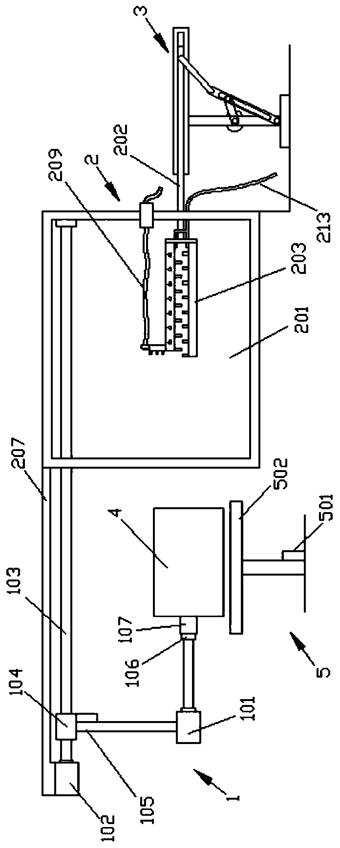
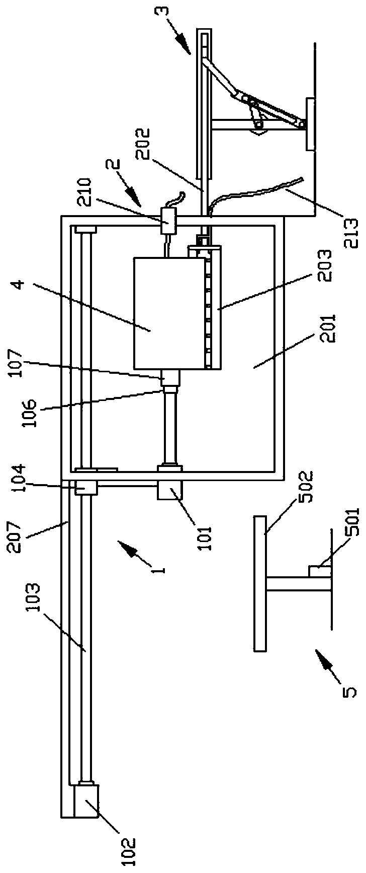
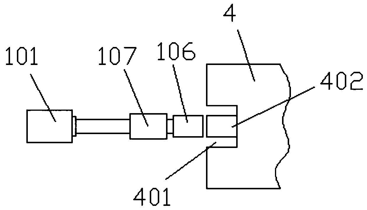
[0031] Such as Figure 1-Figure 4 As shown, a trash can is roughly cylindrical or cuboid in shape, including a cavity 401 located at the bottom of the barrel, and a first stud 402 is provided in the center of the cavity 401;

[0032] A device for cleaning the above-mentioned trash can, comprising a driving mechanism 1 and a cleaning device 2, the driving mechanism 1 includes a second stud 106 docked with the first stud 402, the second stud 106 is horizontally arranged, The left side of the second stud 106 is also provided with a first drive motor 101 and a connecting sleeve 107, and the inner wall of the connecting sleeve 107 is provided with an internal thread (not shown) that is matched with the first stud 402 and the second stud 106. Specifically, the power output end of the first driving motor 101 is connected to the left end of the second stud 106. When the connecting sleeve 107 is not in use, its state is set on the power output shaft of the first driving motor 101. The ...


PUM


Abstract

The invention discloses efficient cleaning equipment of an environment-friendly waste container and relates to the technical field of environment-friendly equipment. The efficient cleaning equipment comprises a driving mechanism and a cleaning device. The waste container is detachably connected to the driving mechanism. The driving mechanism comprises a first driving motor and a second driving motor. The power output end of the second driving motor is connected with a lead screw. A linkage block sleeves the lead screw. A second electric telescopic rod is arranged at the bottom of the linkage block. The power telescopic end of the second electric telescopic rod is connected with the first driving motor. The cleaning device comprises a cleaning room. The second driving motor and the lead screw are arranged at the top of the cleaning room. A movable rod penetrates through the cleaning room. A U-shaped brush body is mounted at one end of the movable rod. A driving device is arranged at theother end of the movable rod. A spraying device and a drying device are arranged on the brush body. The cleaning equipment provided by the invention has the advantages of good cleaning effect and high efficiency and is environmentally friendly and sanitary.

Description

technical field [0001] The invention relates to the technical field of environmental protection equipment, in particular to an efficient cleaning equipment for an environmental protection trash can. Background technique [0002] Garbage cans are containers for "staining dirt and dirt" in people's lives, and they are also a reflection of social culture. There are a large number of trash cans in urban communities, office areas and streets for garbage storage. Sanitation workers and cleaning personnel After the trash can is transported and dumped, considering the sanitation and environmental protection of the environment around the trash can, it is necessary to clean the trash can. In the prior art, most of the cleaning is manual, that is, the cleaning staff sprays the trash can with a flushing gun. Flushing, this cleaning method has the disadvantages of poor cleaning effect and low efficiency, and the wall of the trash can after cleaning is wet, easily contaminated with dirt, ...

Claims


Application Information

Patent Timeline
IPC IPC(8): B08B9/34B08B9/36F26B21/00
CPCB08B9/34B08B9/36F26B21/00
Inventor 岳左文岳左兵曹克芳庄士荣
Owner 合肥博创机械制造有限公司
Why Eureka
Try Eureka