
Thin-wall steel pipe clamping device

A technology of clamping device and thin-walled steel pipe, which is applied in the direction of auxiliary devices, tubular objects, applications, etc., can solve the problems of single operation and action mode of the clamp, and can not be assembled automatically, and achieve compact structure, high assembly efficiency, clamping reliable effect

Inactive Publication Date: 2019-08-23
ZHEJIANG UNIV OF TECH
View PDF0 Cites 0 Cited by
  • Summary
  • Abstract
  • Description
  • Claims
  • Application Information

AI Technical Summary

Problems solved by technology

However, the assembly of the existing pilot valve is mainly manual, and the corresponding fixture operation and action mode are relatively simple.
The singleness of the fixture is mainly reflected in the following two points: First, there is often only one type of assembly fixture that meets the conditions for a certain function of the valve body, that is, one type of valve body can only use one kind of fixture; secondly, it cannot be used for automatic assembly

Method used


Image

  • Thin-wall steel pipe clamping device
  • Thin-wall steel pipe clamping device
  • Thin-wall steel pipe clamping device

Examples


Embodiment Construction

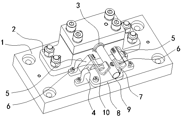
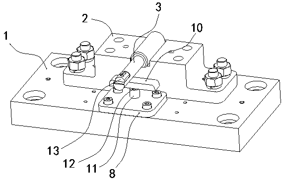
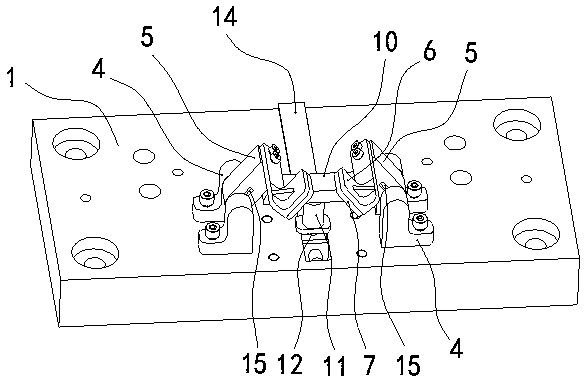
[0011] The specific embodiment of the thin-walled steel pipe clamping device of the present invention is as figure 1 , figure 2 , image 3 As shown, it includes a base 1, a mandrel 3 that is fixedly installed above the base 1 and extends forward and backward, and a clamping mechanism and a release mechanism that are installed on the base 1 and cooperate with the mandrel 3. The clamping mechanism includes 3 Two mounting seats 4 symmetrically arranged on the left and right sides of the axis, two connecting arms 5 mounted on the corresponding mounting seats 4 and two pressure plates 6 fixedly mounted on the corresponding connecting arms 5, the rotation axis of the connecting arms 5 and the plate surface of the pressure plate 6 They are all parallel to the axis of the mandrel 3, and between the two connecting arms 5 and the corresponding mounting seats 4 are respectively installed torsion springs 15 that drive the pressure plate 6 to be pressed against the surface of the mandrel...


PUM


Abstract

The invention discloses a thin-wall steel pipe clamping device. The clamping device comprises a base, a mandrel, a clamping mechanism and a releasing mechanism, wherein the mandrel extends forwards and backwards and is fixedly arranged above the base, and the clamping mechanism and the releasing mechanism are arranged on the base and matched with the mandrel; the clamping mechanism comprises two mounting seats, two connecting arms, torsional springs and two pressing plates, wherein the two mounting seats are arranged in a bilateral symmetry mode with respect to the axis of the mandrel, the twoconnecting arms are arranged on the corresponding mounting seats in a rotating mode, the torsional springs are arranged between the two connecting arms and the corresponding mounting seats, the two pressing plates are fixedly arranged on the corresponding connecting arms, and the rotating axes of the connecting arms and the plate boards of the pressing plates are all parallel to the axis of the mandrel; and the releasing mechanism comprises an ejector rod, wherein the ejector rod is vertically arranged right below the mandrel and is arranged in the base in a guiding and sliding mode, an ejector block in synchronous ejecting and pressing fit with the two connecting arms is fixed at the top end of the ejector rod, and a push rod in transmission connection with the ejector rod through inclined face fit is arranged in the base in a front and rear guiding and sliding mode. The clamping device has the characteristics of being compact in structure, reasonable in operation, reliable in clamping, ingenious in design, high in assembly efficiency and stable in working.

Description

technical field [0001] The invention relates to a valve body assembly tool for a pilot valve, in particular to a thin-walled steel pipe clamping device. Background technique [0002] Pilot valves are auxiliary valves used to manipulate control mechanisms in other valves or components. The valve body of the conventional pilot valve is mainly made of thin-walled steel pipes. When the pilot valve is assembled, the valve body needs to be fixed with a clamp, and then the capillary and the valve body are welded and fixed. Therefore, the clamp is an important tool used in the assembly of the pilot valve. , and its optimization degree plays a key role in the assembly efficiency of the pilot valve. However, the assembly of the existing pilot valve is mainly manual, and the corresponding fixture operation and action mode are relatively simple. The singleness of the fixture is mainly reflected in the following two points: First, there is often only one type of assembly fixture that m...

Claims


Application Information

Patent Timeline
IPC IPC(8): B23K37/053B23K101/06
CPCB23K37/053B23K2101/06
Inventor 罗怡沁
Owner ZHEJIANG UNIV OF TECH
Learn More