
Re-welding repair method for ring weld joint of pipeline

A welding repair and girth weld technology, applied in welding equipment, welding accessories, tubular objects, etc., can solve the problems of unguaranteed welding quality and high welding work intensity, so as to reduce the intensity of manual operation, ensure welding quality, and ensure reliable Effect

Active Publication Date: 2019-08-23
BC P INC CHINA NAT PETROLEUM CORP +3
View PDF7 Cites 12 Cited by
  • Summary
  • Abstract
  • Description
  • Claims
  • Application Information

AI Technical Summary

Problems solved by technology

[0004] The purpose of the present invention is to solve the problems of high welding work intensity and unguaranteed welding quality in the repair of existing girth weld defects, and to provide a method for rewelding repair of pipeline girth welds

Method used


Image

  • Re-welding repair method for ring weld joint of pipeline
  • Re-welding repair method for ring weld joint of pipeline
  • Re-welding repair method for ring weld joint of pipeline

Examples


Embodiment 1

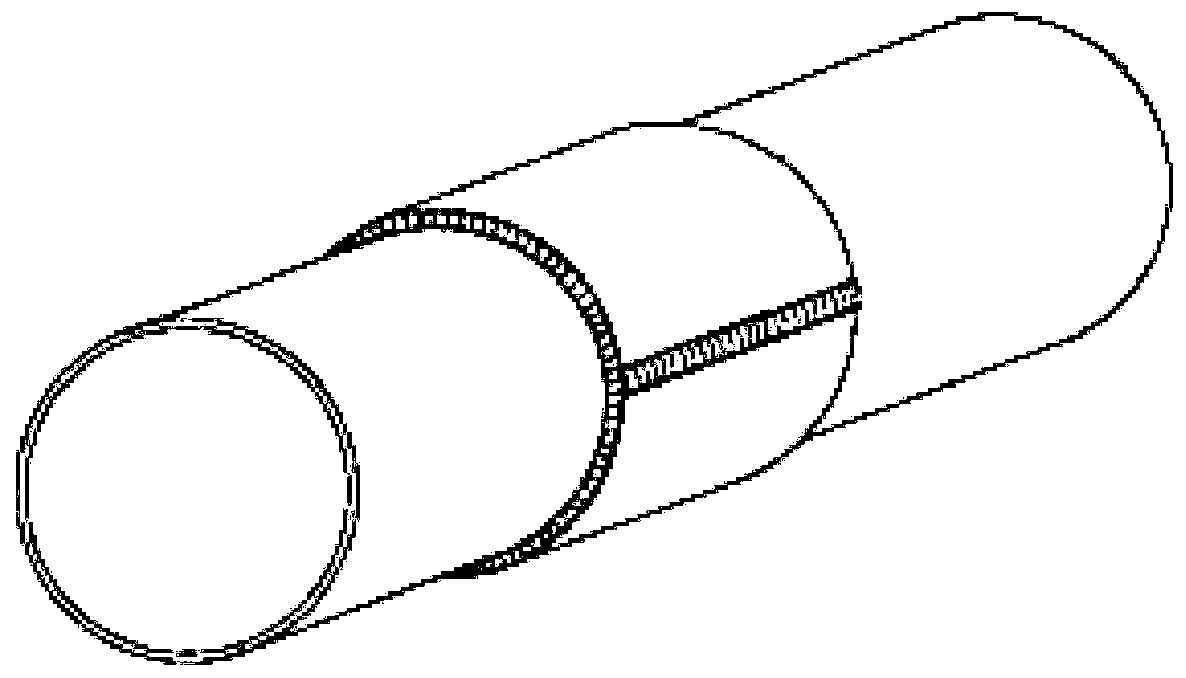
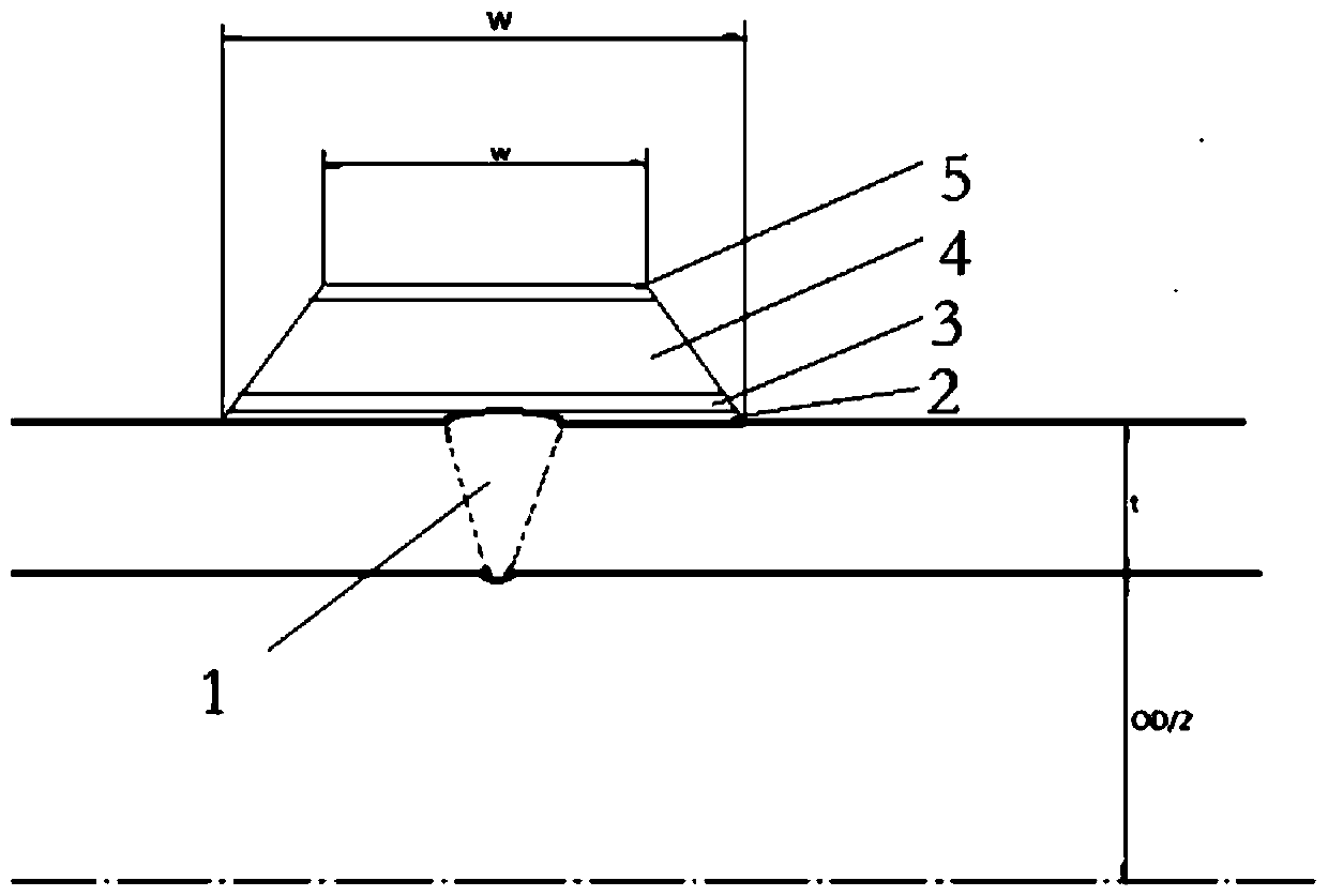
[0051]The in-service pipeline girth weld rewelding (surfacing) repair method provided by the present invention comprises the following steps:

[0052] 1) Clean up and clean the pipe girth weld 1 and adjacent areas;

[0053] 2) Conduct nondestructive testing on the pipeline girth weld 1 and adjacent areas to confirm that the pipeline girth weld 1 is suitable for repair by rewelding (surfacing);

[0054] 3) Arrange strain gauges near the girth weld 1 of the pipeline to monitor the stress and strain in the subsequent link. The steps are as follows: paste strain rosettes on both sides of the weld at points 3', 6', 9' and 12' of the pipeline , paste strain rosettes on alternate sides of the weld at points 1', 2', 4', 5', 7', 8', 10', and 11' of the pipeline. May be close to the original girth weld;

[0055] 4) If necessary, perform depressurization operation on pipeline 7 before pipeline girth welding repair (for example, reduce the pressure of natural gas pipeline 7 to below 80%...

Embodiment 2

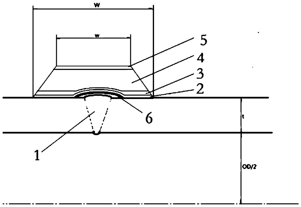
[0074] Embodiment 2 is similar to Embodiment 1, with the difference that: between step 4.1) and step 4.2), the step of setting a separation layer is also included, and a welding separation layer 6 is installed on the repaired part of the girth weld to be re-welded. Such as image 3 and Figure 5 As shown, with the separation layer 6 as the basic mold layer, a shorter "B-type sleeve" is formed on the separation layer 6 by 3D printing (surfacing), so that the formed B-type sleeve bridges the original Both sides of the girth weld. When 3D printing (surfacing welding) is used to form a shorter size "B-type sleeve", the separation layer 6 will not melt the original girth weld, but the 3D printing (surfacing) "B-type sleeve" There is a certain gap between the inner wall and the original girth weld.

[0075] When the welding separation layer 6 is installed, the separation layer 6 is made of low-strength, high-plastic-tough material with a thickness of 1-2mm and a width of 20-25mm....


PUM


Abstract

The invention relates to a re-welding repair method for a ring weld joint of a pipeline. By adoption of the re-welding repair method for the ring weld joint of the pipeline, the problems that when a ring weld joint is repaired in the prior art, the welding intensity is high, and the welding quality cannot be guaranteed are solved. The re-welding repair method for the ring weld joint of the pipeline comprises the following steps that (1) the ring weld joint of the pipeline and an adjacent area are cleaned; (2) nondestructive inspection is conducted on the ring weld joint and the adjacent area of the pipeline; (3) a strain gauge is arranged near the ring weld joint of the pipeline; (4) the ring weld joint of the pipeline is re-welded to be repaired, and the stress strain is monitored in theprocess; (5) nondestructive inspection is conducted on re-welding repair weld bead formed after the ring weld joint of the pipeline is treated in step (4); (6) whether re-welding of the ring weld joint of the pipeline is qualified or not is judged, if yes, step (7) is conducted, and if not, step (4) is conduced; (7) if it is judged that re-welding is qualified, anti-corrosion treatment is conducted on the re-welding repair weld bead; and (8) backfilling recovery treatment is conducted on the pipeline subjected to anti-corrosion treatment.

Description

technical field [0001] The invention relates to the field of oil and gas transmission pipelines, in particular to a method for rewelding and repairing pipeline girth welds, which can be used for emergency maintenance of oil and gas transmission pipelines in service. Background technique [0002] Pipeline transportation is an efficient, convenient and environmentally friendly way of oil and gas transportation. At present, the mileage of long-distance pipelines in use in China is about 80,000 kilometers, which has brought great convenience to modern life. Pipelines are special pressure vessels. During the operation of long-distance oil and gas pipelines, defects in pipelines will occur due to corrosion, stress and other reasons, which will reduce the safety of pipeline operations. Therefore, the pipeline needs to be inspected during its use to detect and repair the defects in the pipeline, such as metal loss (thinning of wall thickness) caused by corrosion, and lack of fusion ...

Claims


Application Information

Patent Timeline
Patent Type & Authority Applications(China)
IPC IPC(8): B23P6/00B23K9/028B23K9/04B23K9/32B23K101/06
CPCB23K9/0282B23K9/042B23K9/32B23P6/00B23K2101/06
Inventor 李记科张鸿博王高峰许彦白强杨锋平聂向晖赵新伟刘迎来
Owner BC P INC CHINA NAT PETROLEUM CORP
Learn More