Steering shaft coupling control system, method and assembly method

A technology of coupling control and steering shaft, applied in steering mechanism, fluid steering mechanism, electric steering mechanism, etc., can solve the problem of increasing energy consumption of vehicle system and achieve the effect of reducing system energy consumption

Active Publication Date: 2020-12-08
HUAWEI TECH CO LTD
View PDF8 Cites 0 Cited by
  • Summary
  • Abstract
  • Description
  • Claims
  • Application Information

AI Technical Summary

Problems solved by technology

[0004] This device for controlling the coupling and decoupling of the first steering shaft and the second steering shaft needs to supply power to the electromagnetic coil all the time when the vehicle is in a mechanical control state, so as to keep the first steering shaft and the second steering shaft in a coupled state for a long time. Obviously, this This coupling and decoupling device increases the system energy consumption of the vehicle

Method used


Image

  • Steering shaft coupling control system, method and assembly method
  • Steering shaft coupling control system, method and assembly method
  • Steering shaft coupling control system, method and assembly method

Examples


Embodiment Construction

[0046] In order to make the purpose, technical solution and advantages of the present application clearer, the implementation manners of the present application will be further described in detail below in conjunction with the accompanying drawings.

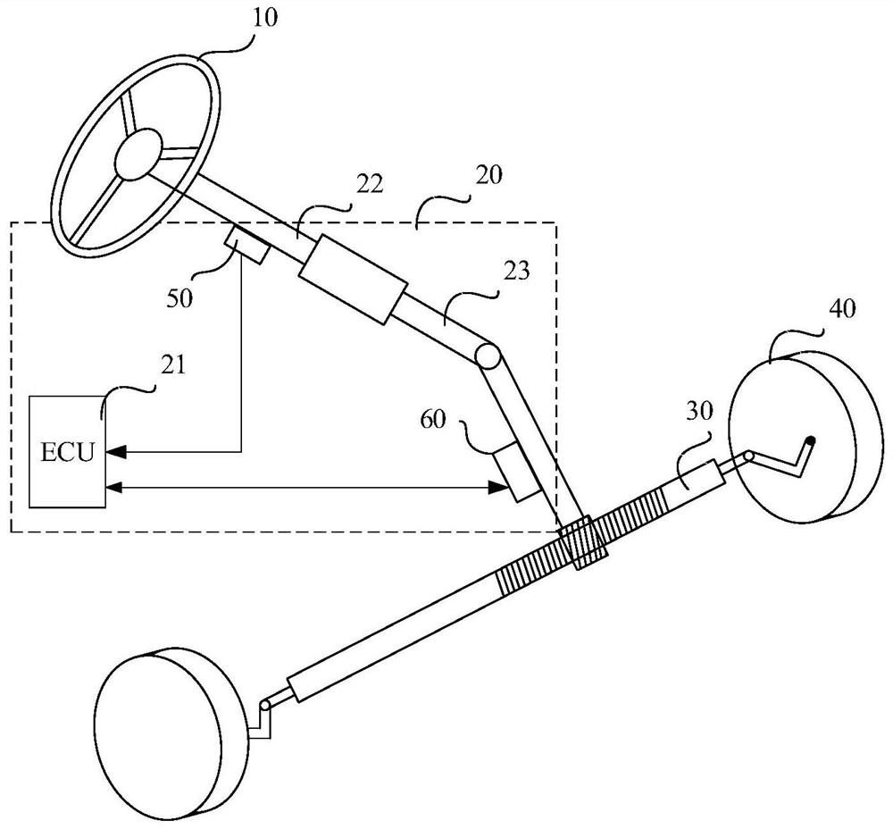
[0047] Please refer to figure 1 , which shows a schematic diagram of the system structure of a steering system applied in an embodiment of the present application. The system structure of the steering system at least includes: a steering wheel 10 , a steering coupling control system 20 , a steering tie rod 30 and a steering wheel 40 . Wherein, the steering coupling control system includes at least an electronic control unit (Electric Control Unit, ECU) 21 and two steering shafts (ie, steering shaft 22 and steering shaft 23 ).

[0048] The steering wheel 10 is mechanically connected to the steering rod 30 through the steering coupling control system 20 , and the two ends of the steering rod 30 are respectively equipped with steeri...


PUM


Abstract

The invention discloses a steering shaft coupling control system and method and an assembling method and belongs to the field of vehicle control. The steering shaft coupling control system comprises afirst steering shaft, a second steering shaft, an immediate shaft and hydraulic equipment which is electrically connected with an electronic control unit ECU, wherein a first inserting slot is formedin one end of the first steering shaft; a second inserting slot is formed in one end of the second steering shaft; sliding splines are correspondingly arranged at the two ends of the immediate shaft;the first end and the second end of the immediate shaft are correspondingly inserted into the first inserting slot and the second inserting slot; a chamber is formed between the immediate shaft and the second inserting slot; a first through hole used for communicating the chamber with the external surface is formed in the second steering shaft; and the first through hole is connected with the hydraulic equipment through an oil passage. As the vehicle does not need to keep the first steering shaft and the second steering shaft to be in a coupled state for a long time by using a mode of alwayssupplying power to an electromagnetic soil when the vehicle is in a mechanical control state, the purpose of reducing system energy consumption of the vehicle is achieved.

Description

technical field [0001] The present application relates to the field of vehicle control, in particular to a steering shaft coupling control system, method and assembly method. Background technique [0002] The Electric Power Steering (EPS) device is a power steering system that relies on the motor to provide auxiliary torque. When the vehicle is in the wire control state, the EPS device directly controls the cornering angle of the steering wheel. When the vehicle is in the mechanical control state, the EPS The device provides the user with assistance in turning the steering wheel. [0003] The steering wheel of the vehicle is connected to the steering wheel through the first steering shaft and the second steering shaft. When the vehicle is in the wire control state, the first steering shaft and the second steering shaft are in a decoupling state (that is, the first steering shaft cannot drive the second steering shaft. Two steering shafts rotate), when the vehicle is in a me...

Claims


Application Information

Patent Timeline
Patent Type & Authority Patents(China)
IPC IPC(8): B62D5/04B62D5/06
CPCB62D5/0421B62D5/064
Inventor 孙中骏张永生张伟
Owner HUAWEI TECH CO LTD
Why Eureka
Try Eureka