
Work boat hook assembly

A technology for working boats and hooks, applied in the direction of manipulating equipment in response to situations, etc., can solve the problems of no emergency response, the release system cannot work, and does not have the function of on-load release, and achieves the effect of quick replacement and convenient switching.

Pending Publication Date: 2019-08-23
中船绿洲镇江船舶辅机有限公司
View PDF0 Cites 0 Cited by
  • Summary
  • Abstract
  • Description
  • Claims
  • Application Information

AI Technical Summary

Problems solved by technology

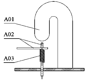
[0002] There are two traditional types of working boat hook device, one is pedal type working boat hook device, which is mainly composed of fixed hook plate A01, protection pin and pedal A02, and return spring A03 (see attached figure 1 ), the opening and closing between the protection pin and the fixed hook plate A01 can be controlled by stepping on the protection pin and the pedal A02 and the return spring A03 below it. This type of hook device is used for single lifting point working boats It is more convenient to use when using it, but when it is applied to the work boat with double hoisting points, there are more people who need to participate in the operation synchronously, the synchronous decoupling cannot be guaranteed during the release process, the on-load release function is not available, and the supporting davit type is limited, etc.
[0003] The other is the remote-controlled working boat hook device, which controls the telescopic movement of the flexible shaft core through the operation of the corresponding handle of the control box by the operator, and then controls the opening (release) and closing (connection) of the hook of the hook device. Although the working boat hook device avoids the defects in the use of the foot-operated working boat hook device, when the flexible shaft fails, the release system will not work
[0004] To sum up, the remote-controlled working boat hook device is better than the pedal-operated working boat hook device, but both of the above two working boat hook devices have more application limitations, and there is no emergency response function in case of failure

Method used


Image

  • Work boat hook assembly
  • Work boat hook assembly
  • Work boat hook assembly

Examples


Embodiment Construction

[0030] The present invention is described in further detail now in conjunction with accompanying drawing. These drawings are all simplified schematic diagrams, which only illustrate the basic structure of the present invention in a schematic manner, so they only show the configurations related to the present invention.

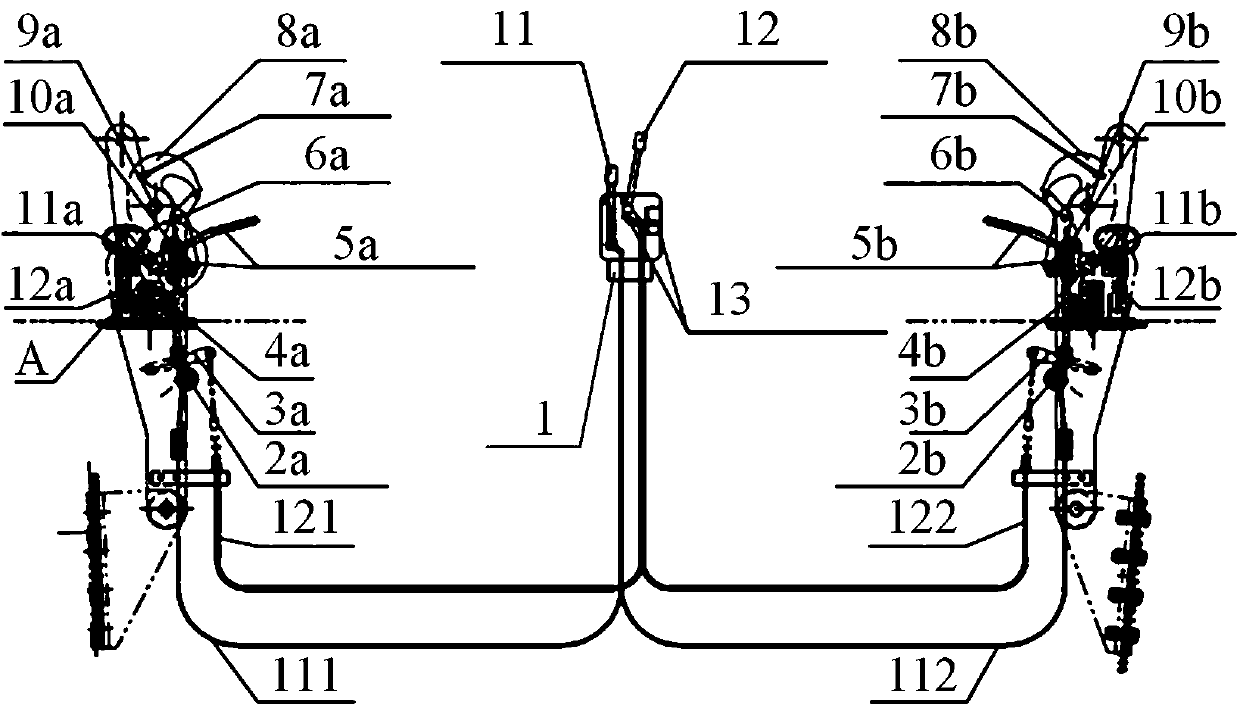
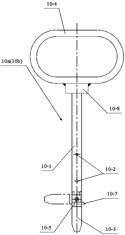
[0031] Such as Figure 2-8As shown, the working boat hook device includes a remote control platform 1, a pull pin control handle 11, a brake block control handle 12, a stop lever and a fixed pin 13, a bow pin pull control flexible shaft 111, and a stern pull pin control flexible shaft 112 , bow brake block control flexible shaft 121, stern brake block control flexible shaft 122, bow pulling pin 2a, stern pulling pin 2b, bow lever arm 3a, stern lever arm 3b, bow tie rod 4a, stern tie rod 4b, bow Brake block and external decoupling pedal 5a, stern brake block and external decoupling pedal 5b, bow cable bracket and bolt 6a, stern cable bracket and bolt 6b, bow g...


PUM


Abstract

The invention relates to a work boat hook assembly which comprises a remote control platform, a pull pin control handle, a brake block control handle, a stop rod and fixing pin, a bow pull pin controlflexible shaft, a stern pull pin control flexible shaft, a bow brake block control flexible shaft, a stern brake block control flexible shaft, a bow pull pin, a stern pull pin, a bow lever force arm,a stern lever force arm, a bow pull rod, a stern pull rod, a bow brake block and external unhooking pedal, a stern brake block and external unhooking pedal, a bow rope stop frame and bolt, a stern rope stop frame and bolt, a bow green locking mark, a stern green locking mark, a bow hook head, a stern hook head, a bow hook shaft, a stern hook shaft, a bow connecting pin, a stern connecting pin, abow brake block shaft, a stern brake block shaft, a bow safety pin and a stern safety pin. Under a normal working condition, remote control mode operation is adopted, when a fault occurs to a remote control operation system, the operation mode can be replaced with a pedal mode or a manual operation mode in time, and therefore operation that a work boat can be smoothly released to the sea surface or recovered back into a mother vessel can be guaranteed no matter the remote control system works normally or not.

Description

technical field [0001] The invention relates to a hook device, in particular to a working boat hook device. Background technique [0002] There are two traditional types of working boat hook device, one is pedal type working boat hook device, which is mainly composed of fixed hook plate A01, protection pin and pedal A02, and return spring A03 (see attached figure 1 ), the opening and closing between the protection pin and the fixed hook plate A01 can be controlled by stepping on the protection pin and the pedal A02 and the return spring A03 below it. This type of hook device is used for single lifting point working boats It is more convenient to use when using it, but when it is applied to the working boat with double hoisting points, it needs more people to participate in the operation synchronously, the synchronous decoupling cannot be guaranteed during the release process, it does not have the function of on-load release, and the type of supporting davit is limited. [0...

Claims


Application Information

Patent Timeline
IPC IPC(8): B63B23/70
CPCB63B23/70
Inventor 苏野徐丽云
Owner 中船绿洲镇江船舶辅机有限公司
Learn More