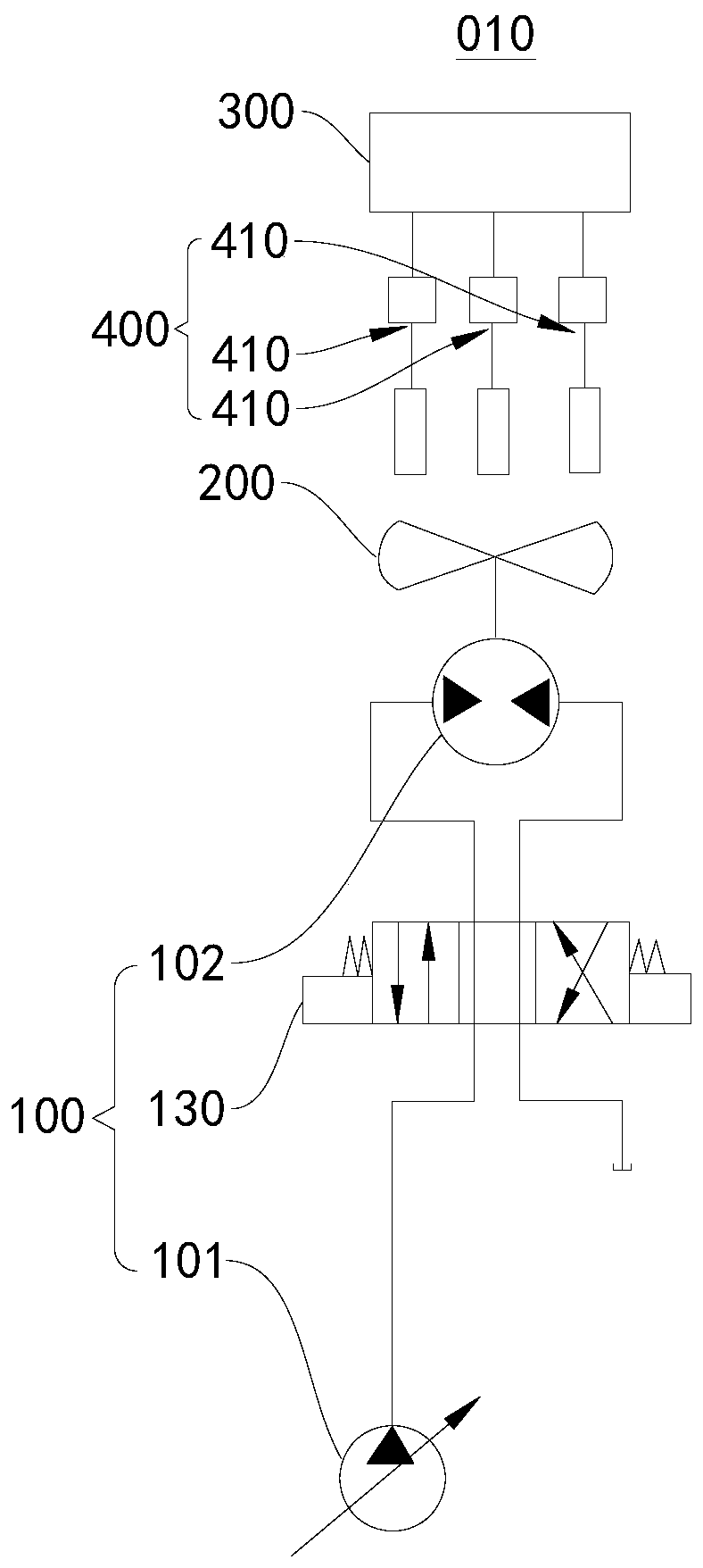
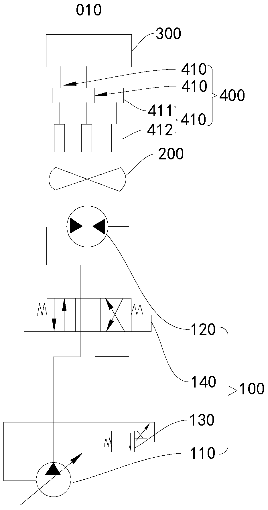
Cooling apparatus, rotary drilling rig, and engine cooling method

A technology of cooling device and rotary drilling rig, which is applied in the direction of engine cooling, machine/engine, engine components, etc., which can solve the problems that it is difficult to guarantee the cooling of the engine, and achieve the effect of effective cooling

Pending Publication Date: 2019-08-23
BEIJING SANY INTELLIGENT MFG TECH CO LTD
View PDF7 Cites 3 Cited by
  • Summary
  • Abstract
  • Description
  • Claims
  • Application Information

AI Technical Summary

Problems solved by technology

[0002] Most of the rotary drilling rig engines provided in the related art are diesel engines, and the cooling system used therein includes a coolant cooling assembly, an air cooling assembly and a fuel cooling assembly. The above three cooling assemblies are usually cooled by cooling air provided by a fan. However, the three When heat dissipation components with different heat dissipation media are used to dissipate heat from the engine, they have different heat dissipation capabilities, and when dissipating heat, the temperature of each heat dissipation component is different, and fans with different speeds are required to ensure effective heat dissipation for each heat dissipation component. , but related technologies are difficult to ensure stable cooling of the engine

Method used


Image

  • Cooling apparatus, rotary drilling rig, and engine cooling method
  • Cooling apparatus, rotary drilling rig, and engine cooling method
  • Cooling apparatus, rotary drilling rig, and engine cooling method

Examples


Embodiment Construction

[0024] In order to make the objectives, technical solutions, and advantages of the embodiments of the present invention clearer, the technical solutions in the embodiments of the present invention will be described clearly and completely in conjunction with the accompanying drawings in the embodiments of the present invention. Obviously, the described embodiments It is a part of the embodiments of the present invention, not all the embodiments. The components of the embodiments of the present invention generally described and illustrated in the drawings herein may be arranged and designed in various different configurations. Therefore, the following detailed description of the embodiments of the present invention provided in the accompanying drawings is not intended to limit the scope of the claimed invention, but merely represents selected embodiments of the present invention. Based on the embodiments of the present invention, all other embodiments obtained by those of ordinar...


PUM


Abstract

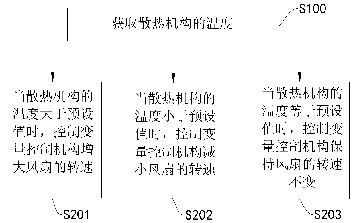
The present invention relates to the technical field of engineering machinery, and specifically relates to a cooling apparatus, a rotary drilling rig, and an engine cooling method. The cooling apparatus includes a variable control mechanism, a fan, a heat dissipation mechanism, and a controller; the variable control mechanism is connected to the fan, and is configured to drive the fan to rotate, so that the heat dissipation mechanism dissipates heat; both the variable control mechanism and the heat dissipation mechanism are electrically connected to the controller, wherein the heat dissipationmechanism includes at least two heat dissipation components, and each heat dissipation component includes a temperature sensor and a radiator; the controller is electrically connected to the temperature sensor, and the temperature sensor is configured to detect temperature of the radiator; the controller is configured to: obtain temperature of each radiator, and control the variable control mechanism to adjust a rotation speed of the fan based on a comparison result between the temperature of each radiator and a preset value of each radiator. In the present invention, the cooling apparatus, the rotary drilling rig, and the engine cooling method can flexibly adjust the rotation speed of the fan based on the temperature of each radiator, so that each radiator has good cooling performance.

Description

Technical field [0001] The present invention relates to the technical field of engineering machinery, in particular to a cooling device, a rotary drilling rig and an engine cooling method. Background technique [0002] Rotary drilling rig engines provided by related technologies are mostly diesel engines. The cooling system used includes coolant heat dissipation components, air heat dissipation components, and fuel heat dissipation components. The above three heat dissipation components are usually cooled by a fan to provide cooling air. When cooling components with different heat dissipation media are used to dissipate the engine, they have different heat dissipation capabilities, and when dissipating heat, the temperature of each heat dissipation component itself is different, and fans with different speeds are required to ensure effective heat dissipation for each heat dissipation component , But related technology is difficult to ensure stable cooling of the engine. Summary ...

Claims


Application Information

Patent Timeline
Patent Type & Authority Applications(China)
IPC IPC(8): F01P7/02F01P7/04F01P5/04
CPCF01P7/026F01P7/044F01P7/02F01P5/04F01P2025/50F01P2025/52
Inventor 张学敏齐文虎于卓伟
Owner BEIJING SANY INTELLIGENT MFG TECH CO LTD
Why Eureka
Try Eureka