Piercing electrical connector

An electrical connector and piercing technology, which is applied in the field of piercing electrical connectors, can solve the problems of unreasonable connector structure design, increased connector packaging cost, electrical accidents in electrical appliances, etc., so as to reduce assembly costs and improve Production efficiency, easy packaging effect

Pending Publication Date: 2019-08-23
DONGGUAN HONGRU CONNECTORS CO LTD
View PDF0 Cites 5 Cited by
  • Summary
  • Abstract
  • Description
  • Claims
  • Application Information

AI Technical Summary

Problems solved by technology

[0002] In order to facilitate the connection of cables, the prior art connector has the technology of using piercing terminals to pierce the cable to realize rapid connection. Due to the unreasonable structure design of the connector in the prior art, the existing connector must Packed in a tray to prevent the cable from being plugged in normally due to the tightness of the cover shell and the rubber shell due to the collision between the connectors, which will greatly increase the packaging cost of the connector
[0003] Moreover, when the existing connector is connected to the cable, it is necessary to manually assemble the crimped external wire into the plastic shell. This method has many disadvantages. For example, manual assembly is prone to errors, which will cause electrical appliances Occurrence of electricity accidents

Method used


Image

  • Piercing electrical connector
  • Piercing electrical connector
  • Piercing electrical connector

Examples


no. 1 example

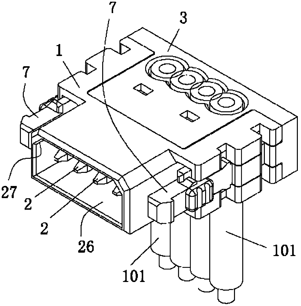
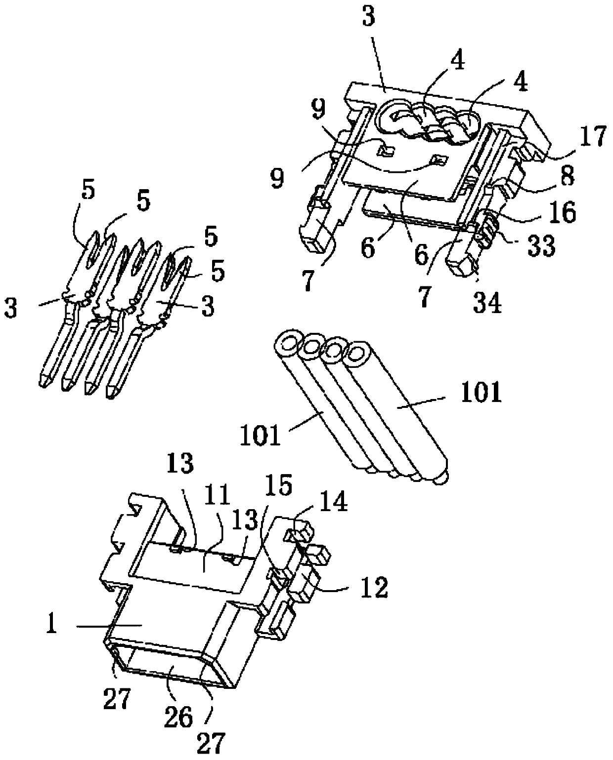
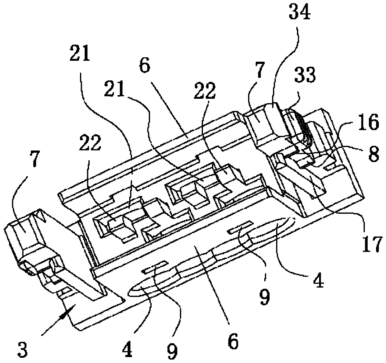
[0045] see Figure 1 to Figure 5 As shown, a piercing type electrical connector of the present invention includes a wire end connector, and the wire end connector has a wire end body 1, a wire end terminal 2 arranged on the wire end body 1, and a snap fit with the wire end body 1 The wire cover 3, the wire end body 1 and the wire cover 3 are all made of insulating plastic. According to the actual needs, the cable 101 can be inserted into the cable or scattered wires, for example, the cable 101 can be commonly used AWG22, AWG24, or AWG26, etc., adjust the aperture of the wire hole 4 for different wire numbers Size is fine. Preferably, the wire holding hole 4 runs through the wire cover 3 , so that after the cable 101 is installed in the wire holding hole 4 , the user can easily see whether the cable 101 is installed in an accurate position. The wire end terminal 2 has a piercing portion 5, and the piercing portion 5 is used to pierce the insulation layer of the cable 101 cont...

no. 2 example

[0083] see Figure 9 As shown, in this embodiment, the board end connector is installed horizontally, and the board end connector includes an insulating body 45, a conductive terminal 46 installed on the insulating body 45, and two reinforcing solder joints installed on the left and right sides of the insulating body 45. Sheet 47. The structure of the insulating body 45 is substantially the same as that of the board end body 28 , and the structure of the conductive terminal 46 is substantially the same as that of the board end terminal 29 , which will not be repeated here. The reinforcing solder leg 41 has the same structure as the reinforcing solder piece 47 .

[0084] The insulating body 45 has a tongue plate 48 protruding from the middle of the front end of the insulating body 45. The tongue plate 48 is parallel to the external circuit board 102. The conductive terminal 46 has a soldering plate portion 49 and an elastic conductive portion 51. The soldering plate portion 4...


PUM


Abstract

The invention relates to the technical field of electrical connectors, and in particular to a piercing electrical connector, comprising a wire end connector having a wire end body, a wire end terminal, and a wire cover snap-fitted with the wire end body. The wire cover has a line accommodating hole. The wire end terminal has a piercing portion. The wire cover has a buckle plate, a buckle arm and afirst buckle. The buckle plate is provided therein with an engagement hole. The wire end body has a buckle groove, a buckle hole, an engagement bump located in the buckle groove, a pre-locking grooveand a locking groove which communicate with the buckle hole. When the wire end connector needs to be transported or conveyed, the first buckle protrudes into the pre-locking groove and the engagementbump is abutted against the free end of the buckle plate, so that the wire cover and the wire end body are pre-assembled together, and the piercing portion does not pierce a cable. The electrical connector of the invention avoids a trouble for a wire harness manufacturer caused by the tight combination or separation of the wire cover and the wire end body during transportation, is easy to pack, facilitates cable connection, reduces assembly cost and improves production efficiency.

Description

technical field [0001] The invention relates to the technical field of electrical connectors, and in particular discloses a piercing type electrical connector. Background technique [0002] In order to facilitate the connection of cables, the prior art connector has the technology of using piercing terminals to pierce the cable to realize rapid connection. Due to the unreasonable structure design of the connector in the prior art, the existing connector must Packed in a tray, in case the cover shell and the plastic shell are tightly closed due to the collision between the connectors, which will make the cable cannot be normally plugged in later, which will greatly increase the packaging cost of the connector. [0003] Moreover, when the existing connector is connected to the cable, it is necessary to manually assemble the crimped external wire into the plastic shell. This method has many disadvantages. For example, manual assembly is prone to errors, which will cause electri...

Claims


Application Information

Patent Timeline
Patent Type & Authority Applications(China)
IPC IPC(8): H01R4/2404H01R13/506H01R13/639H01R13/629
CPCH01R4/2404H01R13/506H01R13/639H01R13/629H01R4/242H01R12/67H01R4/2406H01R13/6272
Inventor 朱锋
Owner DONGGUAN HONGRU CONNECTORS CO LTD
Why Eureka
Try Eureka