Power distribution cabinet convenient to overhaul

A technology that facilitates maintenance and power distribution cabinets. It is used in substation/distribution device enclosures, busbar/line layout, and anti-seismic equipment. It can solve problems such as shortening user service life, troublesome installation and disassembly, and short-circuiting of wires, so as to extend service life. , Easy to install and disassemble, improve the effect of safe use

Inactive Publication Date: 2019-08-23
SHANXI GREAT WALL ELECTRIC
View PDF5 Cites 2 Cited by
  • Summary
  • Abstract
  • Description
  • Claims
  • Application Information

AI Technical Summary

Problems solved by technology

[0002] The power distribution cabinet is also called the power control box, which is a kind of distribution box; the power distribution box is divided into the power distribution box and the lighting distribution box, and is the final design of the power distribution system; the traditional power distribution Trouble, it is fixed with screws, installation and disassembly are troublesome, users cannot install and disassemble, it is not conducive to user maintenance and replacement, and there is no protective measure, external impact can easily cause damage to internal parts of the power distribution cabinet, reducing the service life of users. There is no wiring device inside the electric cabinet, and the wires inside the power distribution cabinet are scattered and scattered, which can easily cause a short circuit of the wires and reduce the safety factor of the power distribution cabinet; in view of these defects, it is necessary to design a power distribution cabinet that is easy to overhaul

Method used


Image

  • Power distribution cabinet convenient to overhaul
  • Power distribution cabinet convenient to overhaul
  • Power distribution cabinet convenient to overhaul

Examples


Embodiment Construction

[0024] The following will clearly and completely describe the technical solutions in the embodiments of the present invention with reference to the accompanying drawings in the embodiments of the present invention. Obviously, the described embodiments are only some, not all, embodiments of the present invention. Based on the embodiments of the present invention, all other embodiments obtained by persons of ordinary skill in the art without making creative efforts belong to the protection scope of the present invention.

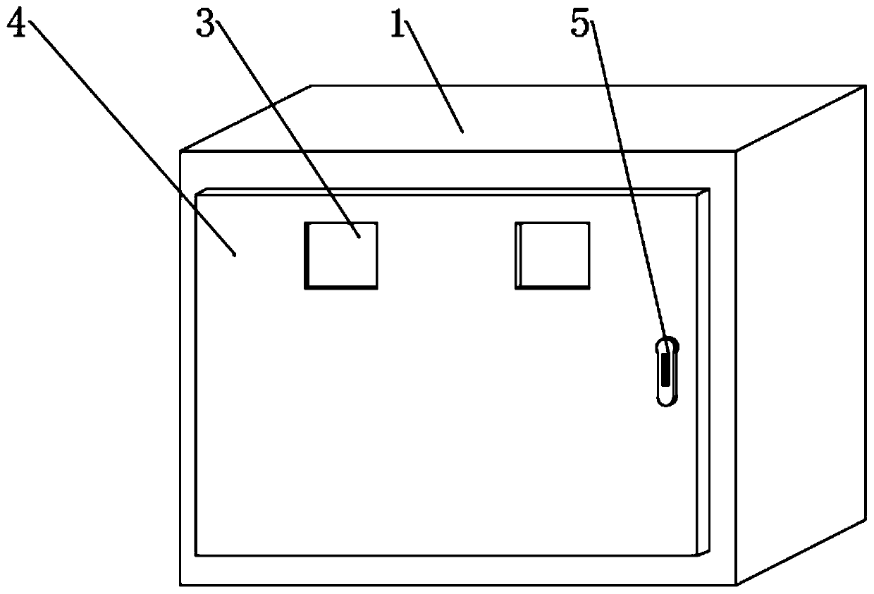
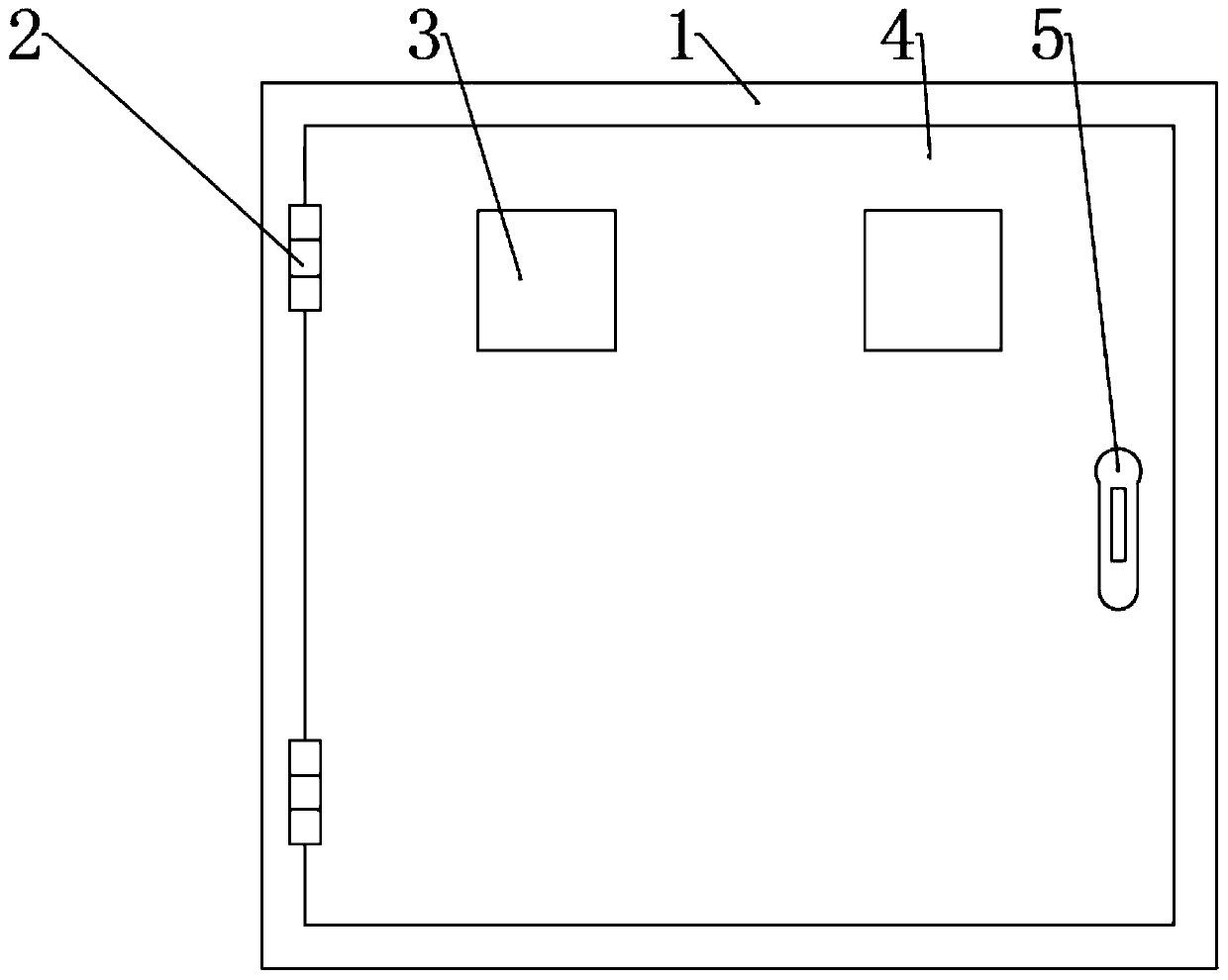
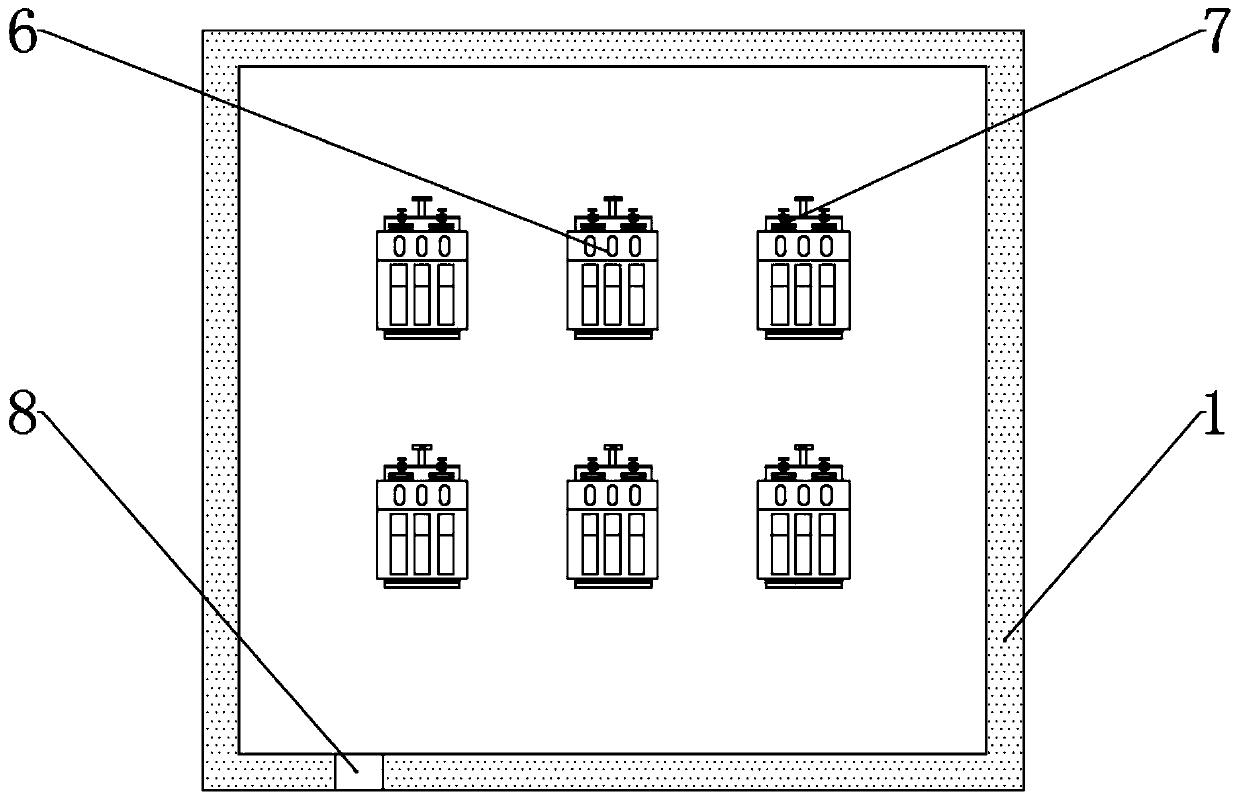
[0025] see Figure 1-7, the present invention provides a technical solution: a convenient maintenance power distribution cabinet, including power distribution cabinet shell 1, hinge 2, observation window 3, cabinet door 4, door lock 5, switch body 6, fixed wire assembly 7 and outlet 8, one side of the shell 1 of the power distribution cabinet is fixed with a hinge 2, one end of the hinge 2 is fixed with a cabinet door 4 by a screw, and the cabinet door 4 is lo...


PUM


Abstract

The invention discloses a power distribution cabinet convenient to overhaul. The power distribution cabinet comprises a power distribution cabinet shell, observation windows, a cabinet door, a door lock, electric brake bodies, a fixed wire tying assembly and a wire outlet. A hinge is fixed to one side of the power distribution cabinet shell through a screw. The cabinet door is fixed at one end ofthe hinge through screws. The cabinet door is located on one side of the power distribution cabinet shell. The door lock is arranged on one side of the cabinet door. The door lock is connected with one side of the power distribution cabinet shell. The observation windows are connected to the two sides of the center of the top of the cabinet door in a sleeving manner. A plurality of electric brakebodies are arranged in the power distribution cabinet shell. A plurality of inverted L-shaped clamping plates are fixed in the power distribution cabinet shell through screws. The power distribution cabinet convenient to overhaul is simple in structure and convenient to operate. The traditional screw fixing mode is abandoned, so that the power distribution cabinet convenient is firmer in fixation.The power distribution cabinet convenient is convenient to mount and dismount. The electric brake bodies can be taken out at will. Therefore, the power distribution cabinet is convenient to overhauland replace for users.

Description

technical field [0001] The invention relates to the technical field of power distribution cabinets, in particular to a convenient power distribution cabinet for maintenance. Background technique [0002] The power distribution cabinet is also called the power control box, which is a kind of distribution box; the power distribution box is divided into the power distribution box and the lighting distribution box, and is the final design of the power distribution system; the traditional power distribution Trouble, it is fixed with screws, installation and disassembly are troublesome, users cannot install and disassemble, it is not conducive to user maintenance and replacement, and there is no protective measure, external impact can easily cause damage to internal parts of the power distribution cabinet, reducing the service life of users. There is no wiring device inside the electric cabinet, and the wires inside the power distribution cabinet are scattered and scattered, which...

Claims


Application Information

Patent Timeline
Patent Type & Authority Applications(China)
IPC IPC(8): H02B1/30H02B1/54H02B1/20
CPCH02B1/20H02B1/30H02B1/54
Inventor 陈良华
Owner SHANXI GREAT WALL ELECTRIC
Why Eureka
Try Eureka