High-power wireless power supply system for floating clearance structure

A technology of wireless power supply and floating structure, applied in the direction of current collectors, electric vehicles, electrical components, etc., can solve the problems of electromagnetic force disturbance, large-scale variation of coupling parameters, complex structure, etc., achieve constant coupling parameters, eliminate electromagnetic radiation, and structure simple effect

Active Publication Date: 2019-08-23
XIDIAN UNIV
View PDF5 Cites 0 Cited by
  • Summary
  • Abstract
  • Description
  • Claims
  • Application Information

AI Technical Summary

Problems solved by technology

[0007] In order to achieve the above purpose, the present invention provides a high-power wireless power supply system for floating clearance structure to solve the problems of large-scale variation of coupling parameters and electromagnetic force disturbance in the current electromagnetic coupling wireless power supply system of floating clearance structure. problems, problems with electromagnetic interference, problems with complex structures and harsh implementation conditions

Method used


Image

  • High-power wireless power supply system for floating clearance structure
  • High-power wireless power supply system for floating clearance structure
  • High-power wireless power supply system for floating clearance structure

Examples


Embodiment 1

[0060] Application of the present invention in a gap wireless power supply system with 28V power supply of a floating structure and a power of 1000W:

[0061] Index requirements: transmission power > 1000W, the transmitting end and the receiving end have no force effect on each other, and the floating clearance is greater than 10mm.

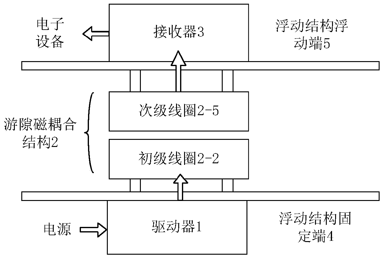
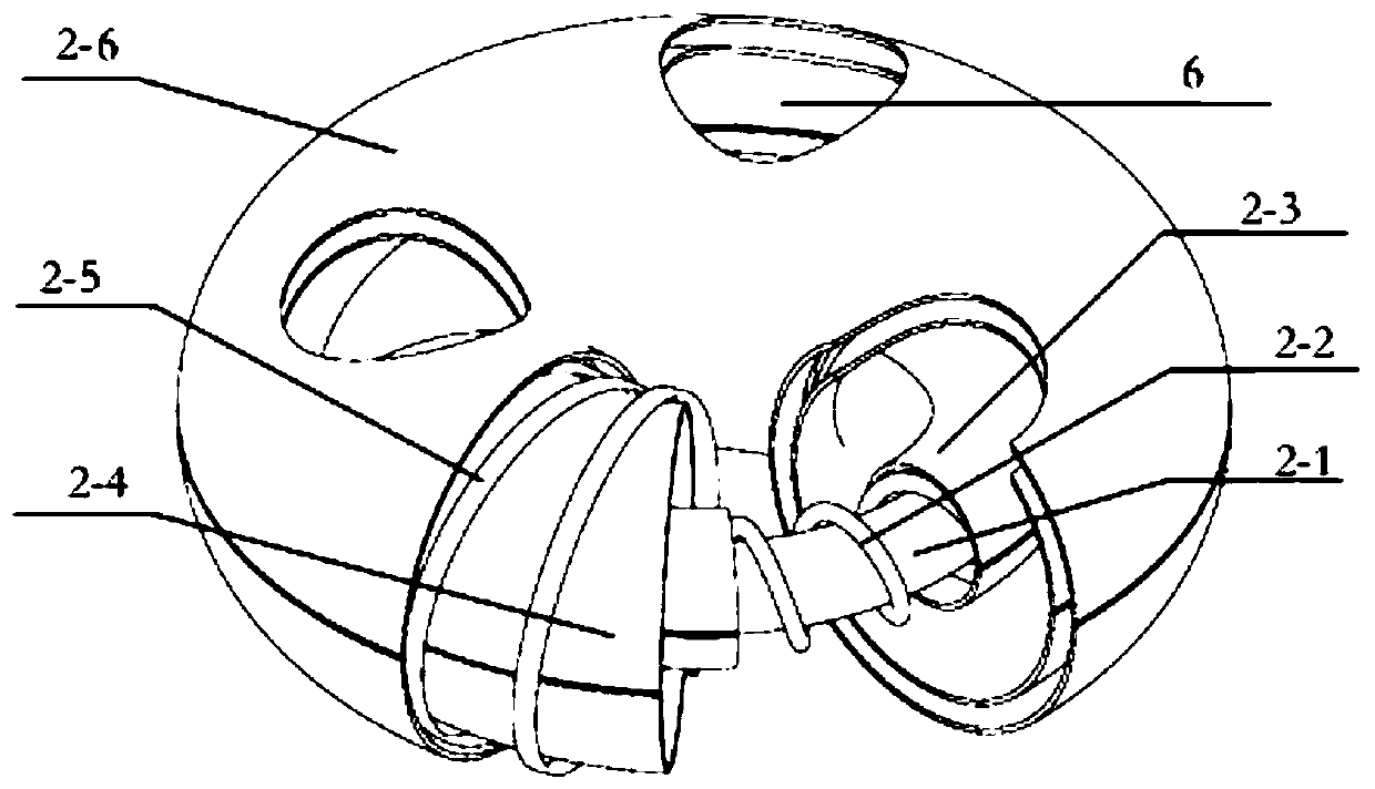
[0062] The structure of the floating structure high-power wireless power supply system is as follows: Figure 4 As shown, it consists of a driver 1, a fixed platform at the transmitting end (fixed end of the floating structure), a gap magnetic coupling structure 2, a receiver 3, and a fixed platform at the receiving end (floating end of the floating structure). The driver 1 converts the energy of the 28V DC power supply After the AC energy with a frequency of 25kHz and a voltage of 28V is supplied to the primary coil 2-2, the AC energy in the primary coil 2-2 generates an alternating magnetic field bound in the magnetic core 2-1. The current and...


PUM


Abstract

The invention discloses a high-power wireless power supply system for a floating clearance structure. The high-power wireless power supply system is composed of a driver, a clearance magnetic couplingstructure and a receiver. The driver is fixedly connected with the fixed end of a floating structure. The receiver is fixedly connected with the floating end of the floating structure. The clearancemagnetic coupling structure is located between the fixed end and the floating end of the floating clearance structure. The primary coil of the clearance magnetic coupling structure is connected with the fixed end of the floating structure. The secondary coil of the clearance magnetic coupling structure is connected with the floating end of the floating structure. The distance between the primary coil and the secondary coil is adjustable. The output end of the driver is electrically connected to the primary coil. The input end of the receiver is electrically connected to the secondary coil. Theclearance magnetic coupling structure comprises a magnetic core, a primary coil uniformly wound around the magnetic core, a primary shielding case integrally wrapping the magnetic core and the primary coil, a first secondary shielding case, a second secondary shielding case and a secondary coil. The problem is solved that a conventional electromagnetic coupling wireless power supply system of thefloating clearance structure has a coupling parameter varying in a large range, electromagnetic force disturbance and electromagnetic interference.

Description

technical field [0001] The invention belongs to the field of wireless power supply, and relates to a high-power wireless power supply system for a floating clearance structure. Background technique [0002] Floating structures are a class of key components in the fields of precision test and metrology, aerospace, inertial navigation / gyroscope, etc. Its principle is to isolate the contact between two sets of mechanical devices by means of suspension, thereby completely eliminating vibration and force transmission, and creating a local mechanically stable environment for precision components. Common floating structures include two-dimensional planar motion mechanisms such as pneumatic floating tables and electromagnetic floating tables, as well as magnetic bearings, two-axis, and three-axis rotating structures. [0003] Floating clearance refers to the air (or vacuum) gap between floating structures, usually ranging from a few millimeters to a few centimeters. The existence ...

Claims


Application Information

Patent Timeline
Patent Type & Authority Applications(China)
IPC IPC(8): H02J7/02H02J50/10H02J50/90H02J50/70H02J5/00
CPCH02J5/005H02J7/025H02J50/10H02J50/70H02J50/90
Inventor 谢楷权磊刘艳刘少伟徐越吴必成
Owner XIDIAN UNIV
Why Eureka
Try Eureka