Pregnant women walk-helping device
A technology for pregnant women and a ring-shaped shell, used in appliances to help people move around, physical therapy, etc., can solve problems such as lack of protection, difficulty in protection, and inability to rest in time
- Summary
- Abstract
- Description
- Claims
- Application Information
AI Technical Summary
Problems solved by technology
Method used
Image
Examples
Embodiment 1
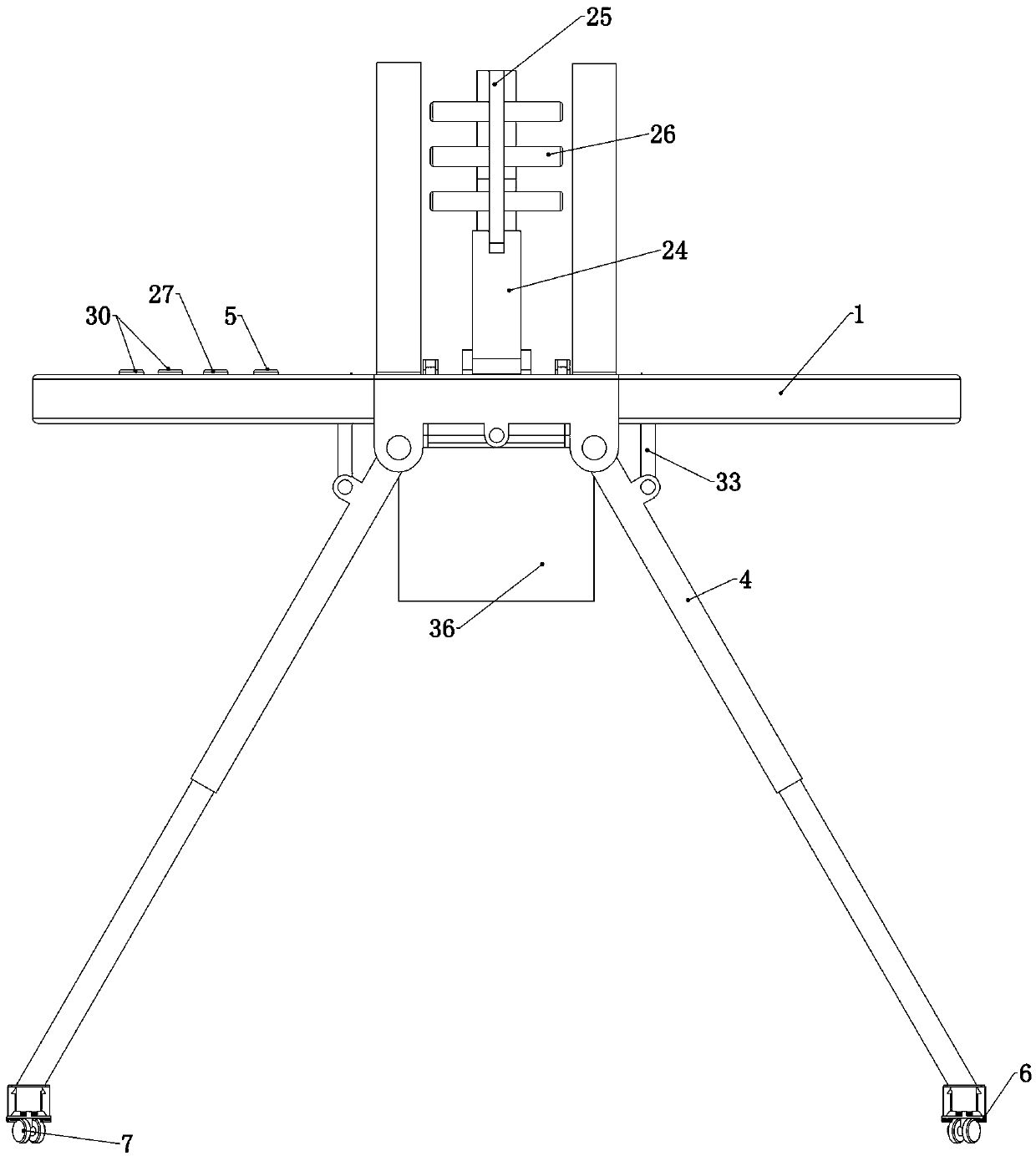
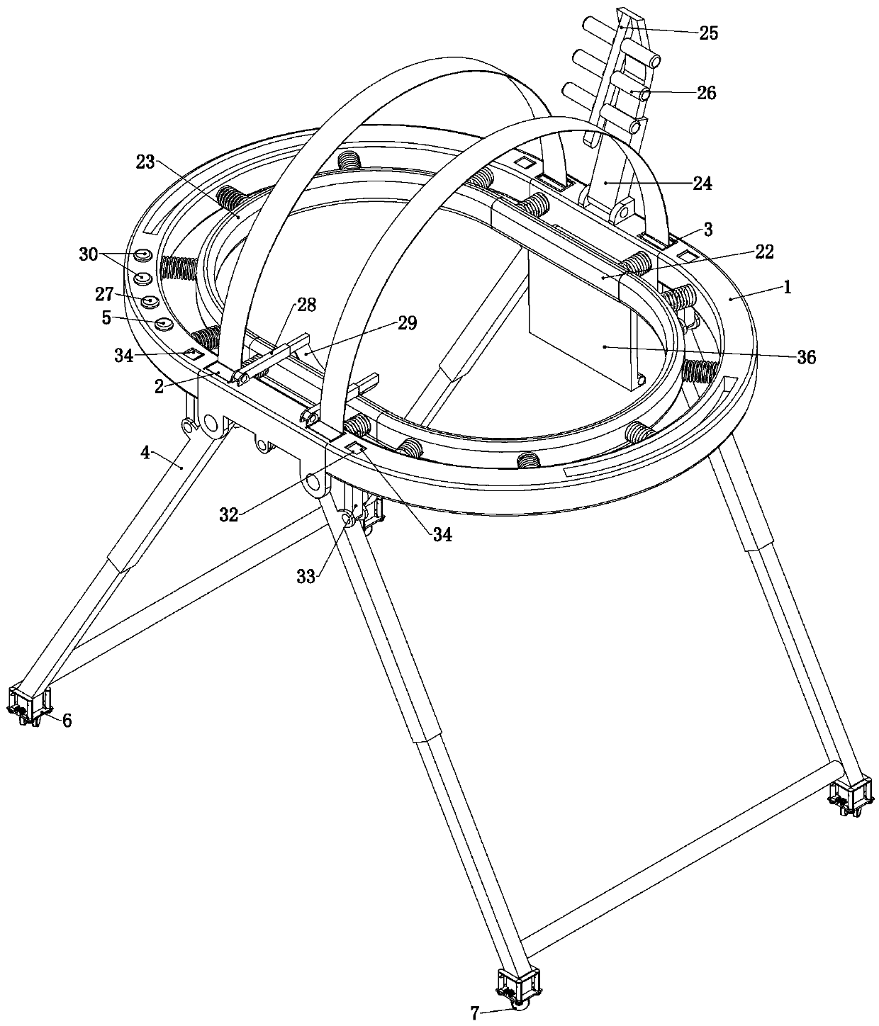
[0034] Embodiment 1, the present invention is a walking aid for pregnant women, which is characterized in that it includes an annular shell 1, which is used to provide a fixed foundation for the subsequent structure, and the user needs to put the annular shell 1 outside the body when using it. The ring is set so as to completely surround and protect the user's body, which can effectively prevent accidental collisions from all directions, and also leaves a certain activity space for the user in the ring shell 1. The front end of the ring shell 1 is set There are two safety belt bases 2 that are slid up and down connected in the annular shell 1, and the relative position of the rear end of the annular shell 1 is provided with two seat belt holders 3 that are slid up and down and connected in the annular shell 1, specifically , a seat belt is wound inside the seat belt base 2, and a seat belt holder 3 is provided directly behind the two seat belt bases 2. Inside the deck 3;
[0...
Embodiment 2
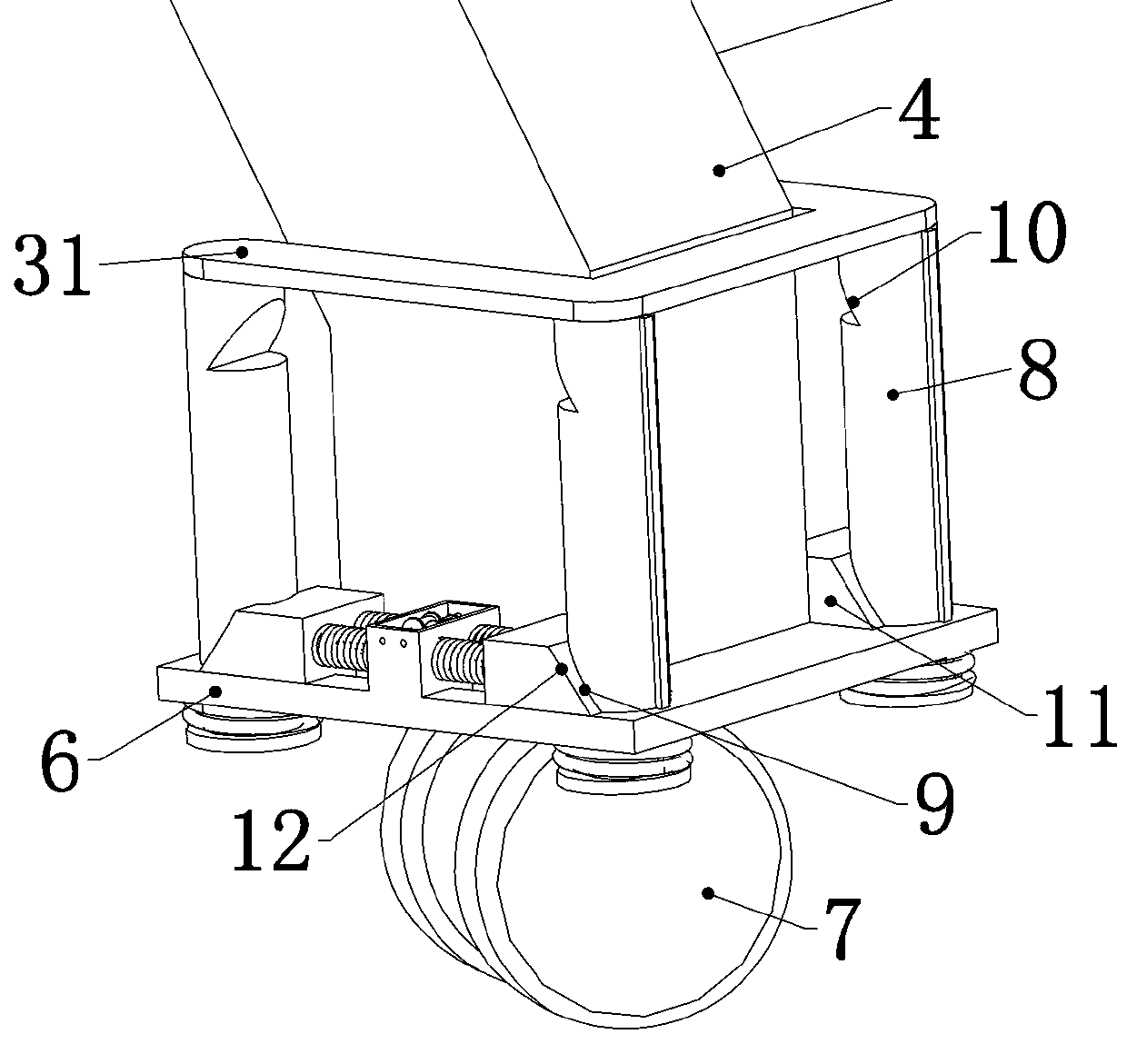
[0036]Embodiment 2. On the basis of Embodiment 1, this embodiment provides a specific structure of a braking device. Because the brake of the universal wheel 7 is to brake the universal wheel 7, the electric telescopic outrigger 4 remains the same. The universal wheel 7 is in contact with the ground, the contact area is small, and the braking effect is not good. Therefore, this embodiment provides a specific braking structure, so that the device can better contact the ground. Specifically, The brake stop device includes four clamping columns 8 that are slidingly connected up and down on the fixed platform 6, and the lower end of each clamping column 8 passes through the corresponding fixed platform 6 and is placed under the fixed platform 6. At the initial position, the four The clamping columns 8 are all placed above the fixed platform 6 and do not contact the ground. When braking is required, the four clamping columns 8 are in contact with the ground, thereby stopping the dev...
Embodiment 3
[0038] Embodiment 3, on the basis of Embodiment 2, this embodiment provides a specific shape of the clamping block 11, the upper clamping slot 10, and the lower clamping slot 9. Specifically, refer to image 3 , Figure 4 , one end of the block 11 is a slope 12, the lower groove 9 includes a slope part 13 and a flat part 14, the upper groove 10 only includes a slope part 13, and the slope part 13 can be connected with the card The inclined surface 12 of the block 11 is attached, and the flat part 14 can be attached to the upper end surface of the block 11. It should be noted that the inclined surface 12 of the block 11 is inclined from the upper right to the lower left, and the upper card slot 10 and The slope part 13 of the lower clamping groove 9 is a slope 12 matching the slope 12 of the clamping block 11, thereby ensuring that the clamping block 11 can limit the upward movement of the clamping column 8, and the plane part 14 of the lower clamping groove 9 can be connected ...
PUM
 Abstract
Description
Claims
Application Information
 - R&D
- Intellectual Property
- Life Sciences
- Materials
- Tech Scout
- Unparalleled Data Quality
- Higher Quality Content
- 60% Fewer Hallucinations
Browse by: Latest US Patents, China's latest patents, Technical Efficacy Thesaurus, Application Domain, Technology Topic, Popular Technical Reports.
© 2025 PatSnap. All rights reserved.Legal|Privacy policy|Modern Slavery Act Transparency Statement|Sitemap|About US| Contact US: help@patsnap.com


