A double-axis multi-directional semi-automatic road step laying device with bottoming and transporting
What is Al technical title?
Al technical title is built by PatSnap Al team. It summarizes the technical point description of the patent document.
A multi-directional, semi-automatic technology, applied in the field of road paving devices and road construction, can solve problems such as low efficiency and waste of manpower, and achieve the effect of not easy to grasp, suitable for grasping, and saving manual handling.
Active Publication Date: 2021-04-16
石岩
View PDF16 Cites 0 Cited by
Summary
Abstract
Description
Claims
Application Information
AI Technical Summary
This helps you quickly interpret patents by identifying the three key elements:
Problems solved by technology
Method used
Benefits of technology
Problems solved by technology
[0004] The object of the present invention is to provide a semi-automatic road step paving device with two axes and multi-directional touch bottoming to solve the problems of wasting manpower and inefficiency in the existing road step laying proposed in the above-mentioned background technology
Method used
Image
Click on the blue label to locate the original text in one second.
Reading with bidirectional positioning of images and text.
Examples
Embodiment 1
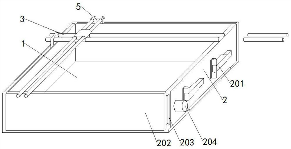
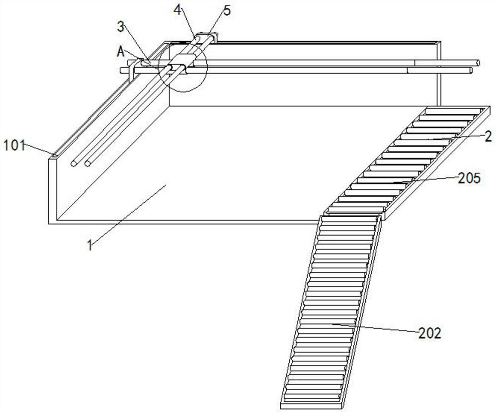
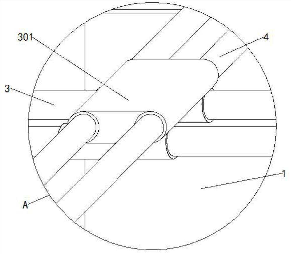
[0027] see Figures 1 to 9, In the embodiment of the present invention, a semi-automatic road step paving device of double-axis and multi-directional bottoming and transporting type includes a placing groove 1, a sliding groove 101, a sliding rod 1011, a sliding path 2, a manual telescopic support rod 201, a tilting Slideway 202, offset gear 203, motor 1 204, small transmission gear 1 2041, large transmission gear 2042, small transmission gear 2 2043, roller 1 205, horizontal bar 3, snap ring 301, vertical bar 4, sliding plate 5. Motor two 501, transmission belt 502, roller two 503, hydraulic rod 6, socket ring 601, socket block 602, sliding hole 6021, contact block 6022, spring one 6023, spring two 6024, fixing rod 603, bracket 604, The rubber plate 605, the threaded fixing rod 606 and the motor 607, the left side and the top of the rear side of the placement slot 1 are nested with the chute 101, the left and right sides of the chute 101 are fixedly connected with the slide b...
PUM
Abstract
The invention provides a semi-automatic road step paving device with two shafts and multiple orientations, which belongs to the technical field of road construction and includes a placement trough, a chute, a slide bar, a slideway, a manual telescopic support rod, and an inclined slideway. , offset gear, motor 1, small transmission gear 1, large transmission gear, small transmission gear 2, roller 1, cross bar, clip ring, vertical rod, sliding plate, motor 2, transmission belt, roller 2, hydraulic rod, Socket ring, socket block, sliding hole, contact block, spring 1, spring 2, fixed rod, bracket, rubber plate, threaded fixed rod and motor, the left side of the slot and the top of the rear side are nested with chute, The left and right sides of the chute are fixedly connected with slide rods, the right side surface of the storage trough is movably connected with a slideway through a hinge, the side surface of the slideway is movably connected with a manual telescopic support rod, and the front surface of the chute is movably connected with an inclined slideway. The top end of the slideway is movably connected with an offset gear through a hinge.
Description
technical field [0001] The invention relates to the technical field of road construction, and more particularly, to the technical field of a paving device for road steps. Background technique [0002] Road steps, also known as road teeth, refer to long-shaped blocks or bricks prefabricated with chiseled stone and concrete. It is paved on the edge of the road to protect the road surface, and it also plays a role in distinguishing the sidewalk from the motor vehicle lane, and plays the role of lifting the sidewalk. In rainy days, the water will flow from the sidewalk to the motor vehicle lane, and the water will flow along the road. The flow of the road steps is more conducive to urban drainage, but the road steps are made of stone or concrete, and the volume and quality are large, and the existing road steps are basically transported to the designated location by trucks and then hoisted manually or by crane. After being lifted to the ground, it needs to be moved and laid man...
Claims
Application Information
Patent Timeline
Application Date:The date an application was filed.
Publication Date:The date a patent or application was officially published.
First Publication Date:The earliest publication date of a patent with the same application number.
Issue Date:Publication date of the patent grant document.
PCT Entry Date:The Entry date of PCT National Phase.
Estimated Expiry Date:The statutory expiry date of a patent right according to the Patent Law, and it is the longest term of protection that the patent right can achieve without the termination of the patent right due to other reasons(Term extension factor has been taken into account ).
Invalid Date:Actual expiry date is based on effective date or publication date of legal transaction data of invalid patent.