Shield tunnel end head frozen earth wall and even wall combined strengthening structure and construction method

A technology of shield tunneling and combined reinforcement, which is applied in infrastructure engineering, tunnels, earthwork drilling and mining, etc., and can solve problems such as high water level under pressure, ineffective consolidation, and failure to form sandy soil layers

Pending Publication Date: 2019-08-27
HAINAN UNIVERSITY
View PDF0 Cites 6 Cited by
  • Summary
  • Abstract
  • Description
  • Claims
  • Application Information

AI Technical Summary

Problems solved by technology

[0004] In areas such as coastal areas, along rivers, and along lakes, especially when the strata at the end of shield tunnels are water-rich sand layers, it is difficult to meet the engineering requirements by using conventional chemical reinforcement methods. Water leakage and sand leakage
The reasons are often: the pressure water level in the end reinforcement area is high, and the cement slurry is easily lost when it penetrates into the sand layer during the construction process. The greater the depth, the stronger the permeability, and the more serious the loss of cement slurry may be. Second, most of the construction period is during the pr

Method used


Image

  • Shield tunnel end head frozen earth wall and even wall combined strengthening structure and construction method
  • Shield tunnel end head frozen earth wall and even wall combined strengthening structure and construction method
  • Shield tunnel end head frozen earth wall and even wall combined strengthening structure and construction method

Examples


Embodiment Construction

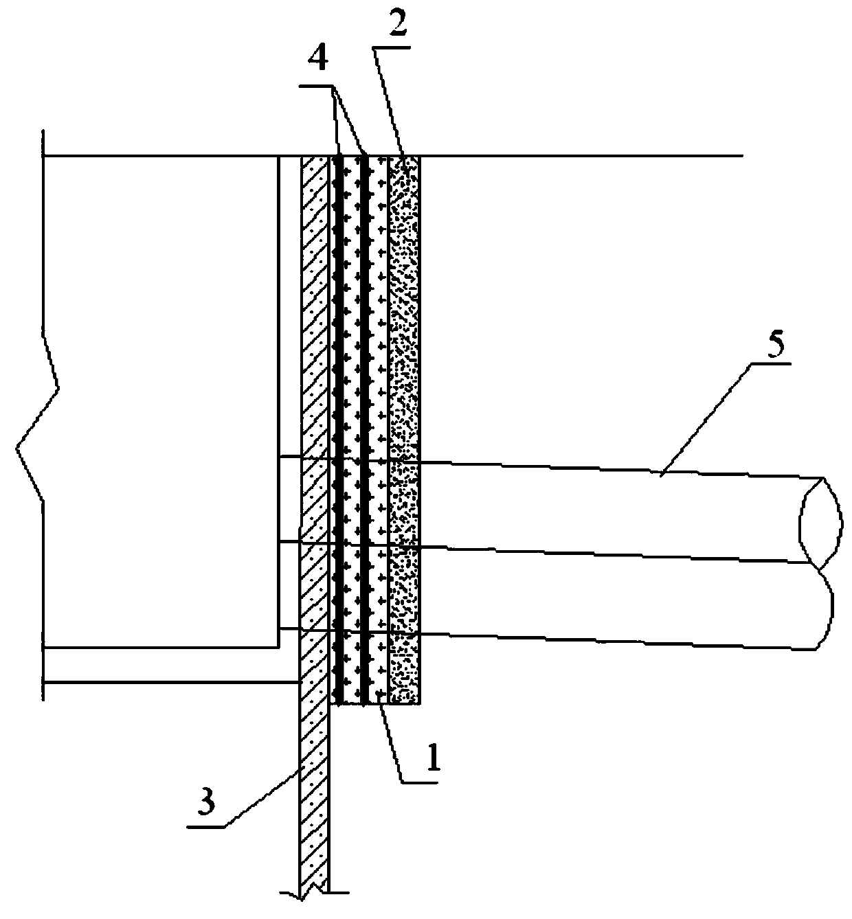
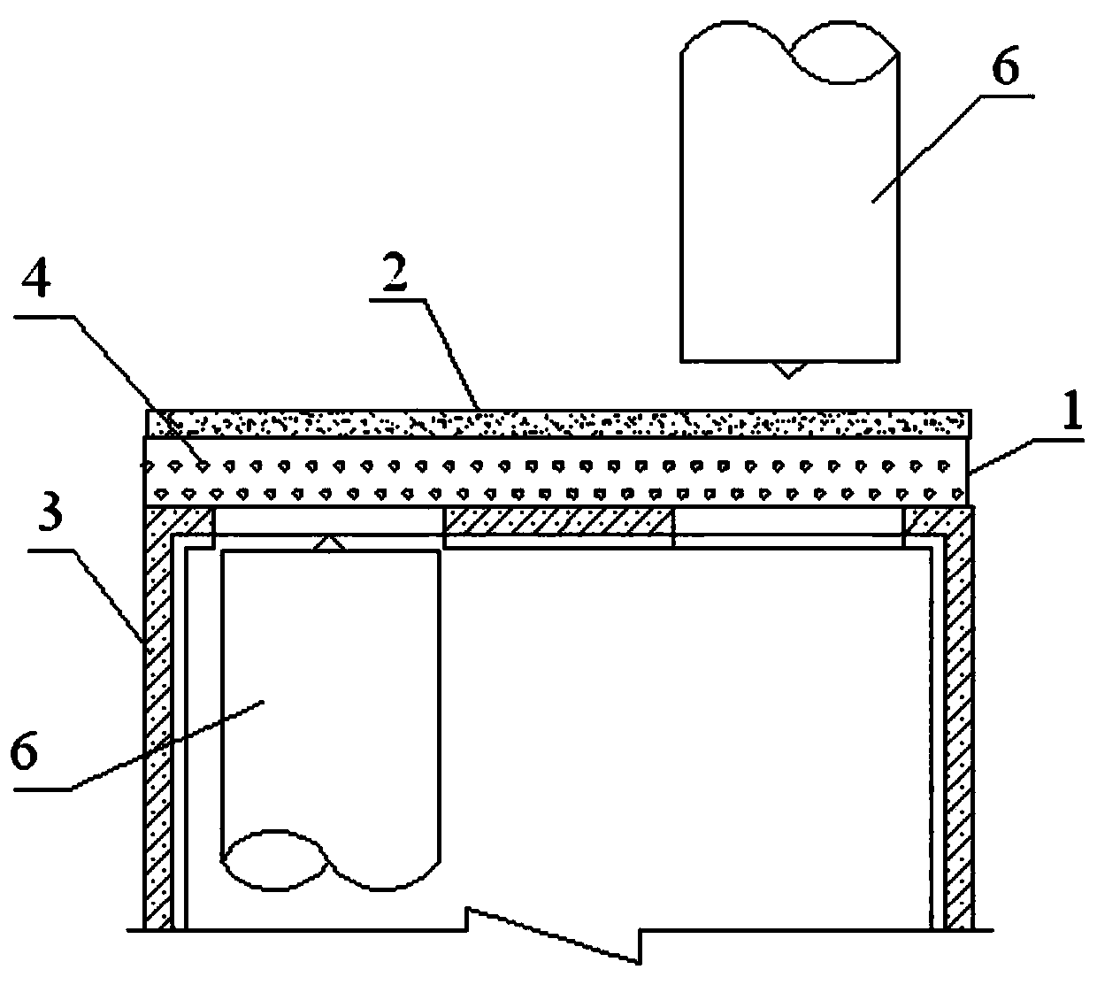
[0196] see Figure 1 to Figure 5 Shown:

[0197] The joint reinforcement structure of the frozen earth wall and the ground connecting wall at the end of the shield tunnel provided by the present invention includes a frozen earth wall 1 and a ground connecting wall 2, wherein the frozen earth wall 2 is arranged at a position close to the enclosure structure 3, and the ground connecting wall The wall 2 is arranged at the rear of the frozen earth wall 1 .

[0198] The frozen soil wall 1 is a vertical frozen soil wall, and the diameter of the frozen pipe 4 in the frozen soil wall 1 is 127mm. The pipe 4 is 300-400mm away from the edge of the groove wall, and the plane length of the frozen pipe 4 is 3m on both sides of the shield tunnel 5, and the frozen pipe 4 is partially frozen within the length of the shield tunnel 5 vault 3m to the depth direction of the arch bottom 3m, Or implement full-length freezing in the depth direction length of 3m from the ground to the bottom of the ...


PUM

PropertyMeasurementUnit
Diameteraaaaaaaaaa
Thicknessaaaaaaaaaa

Abstract

The invention discloses a shield tunnel end head frozen earth wall and even wall combined strengthening structure and a construction method. The combined strengthening structure comprises a frozen earth wall and an even wall, wherein the frozen earth wall is arranged at the position next to an enclosure structure, and the even wall is arranged at the rear portion of the frozen earth wall. The construction method includes the steps that firstly, construction of the even wall is conducted, wherein the construction technology includes surveying and setting out, guide wall manufacturing, slurry mixing, even wall grooving and bottom clearing replacing, glass fiber reinforcement cage or bamboo reinforcement cage machining and lifting, concrete pouring, connector construction, connector pipe ejecting pulling and all-section construction complementation; and secondly, frozen earth wall construction is conducted, wherein according to the construction of the frozen earth wall, before shield tunneling, a manual refrigerating method is used for freezing a water-containing stratum in a working well end head area into a sealed and non-water-permeable curtain, and the frozen earth wall is formed.The shield tunnel end head frozen earth wall and even wall combined strengthening structure and the construction method have the beneficial effects that appropriate strengthening can be conducted onend head stratums rich in water sand layers in areas along seas, rivers, lakes and the like.

Description

technical field [0001] The invention relates to a joint reinforcement structure and a construction method, in particular to a joint reinforcement structure and construction method of a frozen earth wall and a ground connection wall at the end of a shield tunnel. Background technique [0002] At present, the reinforcement of shield tunnel end is a key link in the construction of shield tunneling method, which has great construction risks. When the shield enters and exits the hole, the ground connection wall in the hole area must be broken first, and all steel bars must be cut off. The time required for demolition of the cave door is very tight and the construction is difficult. After the portal is demolished, the strength and sealing of the reinforced body are very high. If the reinforcement effect is not good, the gap between the shield and the portal and the surface settlement will easily occur during the demolition of the portal, which will endanger the nearby underground...

Claims


Application Information

Patent Timeline
IPC IPC(8): E21D9/00E02D19/14E02D19/18E02D5/18
CPCE02D5/18E02D19/14E02D19/18E02D2250/0023E21D9/001
Inventor 胡俊巢达刘勇
Owner HAINAN UNIVERSITY
Why Eureka
Try Eureka