Engineering pipeline offset detecting device based on cutting magnetic induction line principle

A technology for cutting magnetic field lines and offset detection. It is used in measuring devices, mechanical measuring devices, and electrical devices. It can solve problems such as reducing product quality, affecting air-tightness, and inability to install, so as to increase linkage and Effects for synchronization, efficiency and effectiveness

Active Publication Date: 2019-08-27
陈昱见
View PDF8 Cites 5 Cited by
  • Summary
  • Abstract
  • Description
  • Claims
  • Application Information

AI Technical Summary

Problems solved by technology

[0002] When laying engineering pipelines, it is necessary to weld or pre-assemble two sections of pipelines of the same specification. At this time, it is necessary to ensure the concentricity between the two sections of pipelines. If the central axes of the two sections of pipelines are not on a straight line, they are not concentric. At this time It may cause the fit gap between the two to be too large or the installation may not be possible due to the size tolerance. At the same time, if the two sections of pipes are offset during the welding or installation process, it will cause insufficient welding or missing welding. While affecting the airtightness of the subsequent delivery, the quality of the product is reduced, and it is easy to cause leakage and shorten the service life due to insufficient airtightness

Method used


Image

  • Engineering pipeline offset detecting device based on cutting magnetic induction line principle
  • Engineering pipeline offset detecting device based on cutting magnetic induction line principle
  • Engineering pipeline offset detecting device based on cutting magnetic induction line principle

Examples


Embodiment Construction

[0035] The following will clearly and completely describe the technical solutions in the embodiments of the present invention with reference to the accompanying drawings in the embodiments of the present invention. Obviously, the described embodiments are only some, not all, embodiments of the present invention. Based on the embodiments of the present invention, all other embodiments obtained by persons of ordinary skill in the art without making creative efforts belong to the protection scope of the present invention.

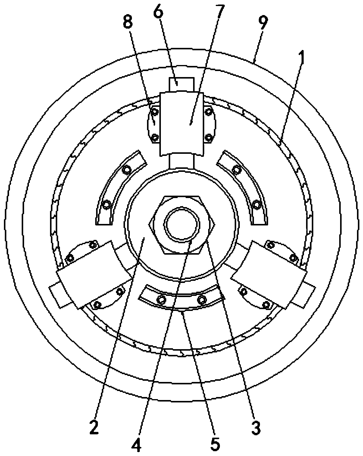
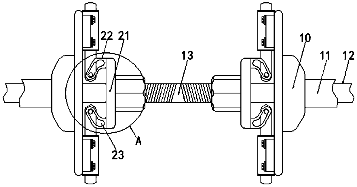
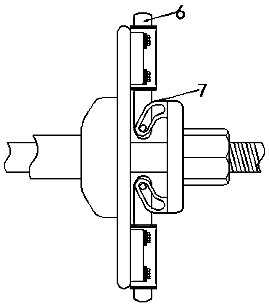
[0036] see Figure 1-14 :

[0037] The engineering pipeline offset detection device based on the principle of cutting magnetic induction lines includes a base plate 1, an adjustment mechanism 2, a threaded sleeve 3, a screw rod 4, a limit block 5, a clamp block 6, a clamp seat 7, a fixed seat 8, a workpiece 9, A cavity 10 , a shaft sleeve 11 , a transmission shaft 12 , a bidirectional threaded area 13 , a first ring magnet 14 , a first conductor plate 15 , a ...


PUM


Abstract

The present invention discloses an engineering pipeline offset detecting device based on the cutting magnetic induction line principle, and relates to the technical field of construction engineering.The device comprises two bottom plates; the middle part of two opposite sides of the two bottom plates is movably connected with an adjusting mechanism; the front side of the adjusting mechanism is fixedly connected with a threaded sleeve; the inner part of the threaded sleeve is movably connected with a screw; and the front surface of the bottom plates is movably connected with three limiting blocks, the shape specifications of the three limiting blocks are the same, the limiting block is a curved structure, and the center of the limiting block is the same as the center of the bottom plate. According to the engineering pipeline offset detecting device based on the cutting magnetic induction line principle provided by the present invention, the change of the induced electromotive force when the conductor cuts the magnetic induction line is used to detect whether the workpiece is offset, and when the workpiece is offset, positions of the first conductor plate and the second conductor plate change; and the magnetic induction line is cut, and the induced electromotive force changes, so that by using the process and the principle, the position of the workpiece can be accurately and intuitively detected.

Description

technical field [0001] The invention relates to the technical field of construction engineering, in particular to an engineering pipeline offset detection device based on the principle of cutting magnetic induction lines. Background technique [0002] When laying engineering pipelines, it is necessary to weld or pre-assemble two sections of pipelines of the same specification. At this time, it is necessary to ensure the concentricity between the two sections of pipelines. If the central axes of the two sections of pipelines are not on a straight line, they are not concentric. At this time It may cause the fit gap between the two to be too large or the installation may not be possible due to the size tolerance. At the same time, if the two sections of pipes are offset during the welding or installation process, it will cause insufficient welding or missing welding. While affecting the airtightness of the subsequent delivery, the quality of the product is reduced, and it is ea...

Claims


Application Information

Patent Timeline
Patent Type & Authority Applications(China)
IPC IPC(8): G01B7/02G01B5/00
CPCG01B5/0002G01B7/02
Inventor 黄圣扬
Owner 陈昱见
Why Eureka
Try Eureka