Food processing machine with good noise reduction effect
A food processing machine, noise reduction technology, applied in the direction of sounding equipment, instruments, household appliances, etc., can solve the problem of high noise, achieve the effect of noise reduction, simple structure, and convenient use
- Summary
- Abstract
- Description
- Claims
- Application Information
AI Technical Summary
Problems solved by technology
Method used
Image
Examples
Embodiment 1
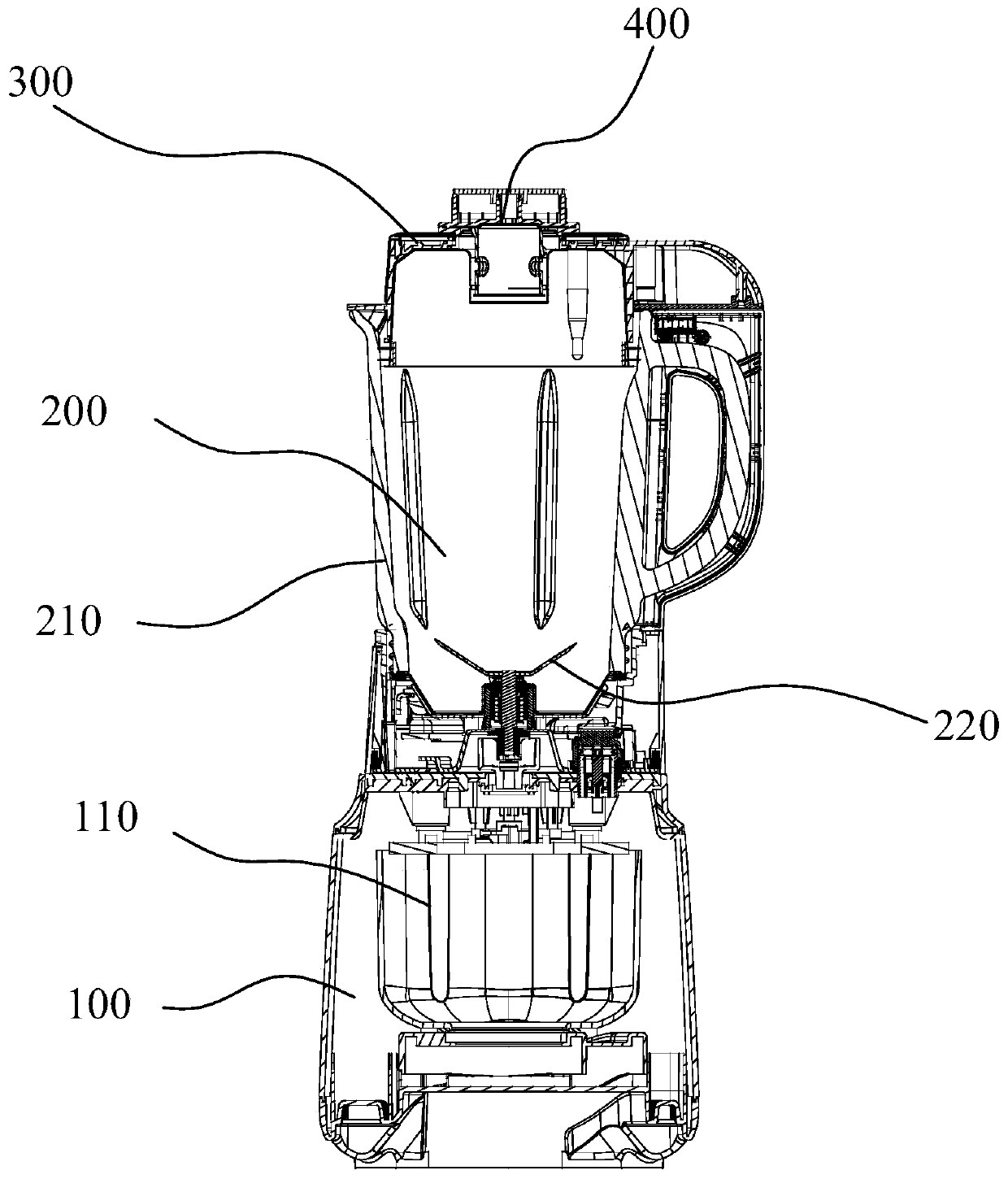
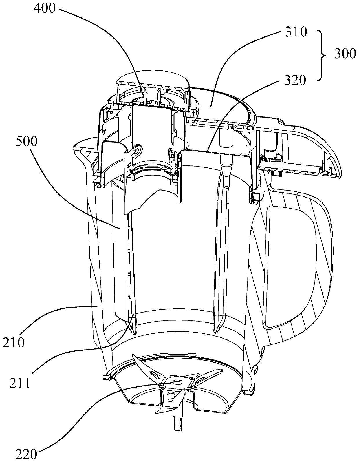
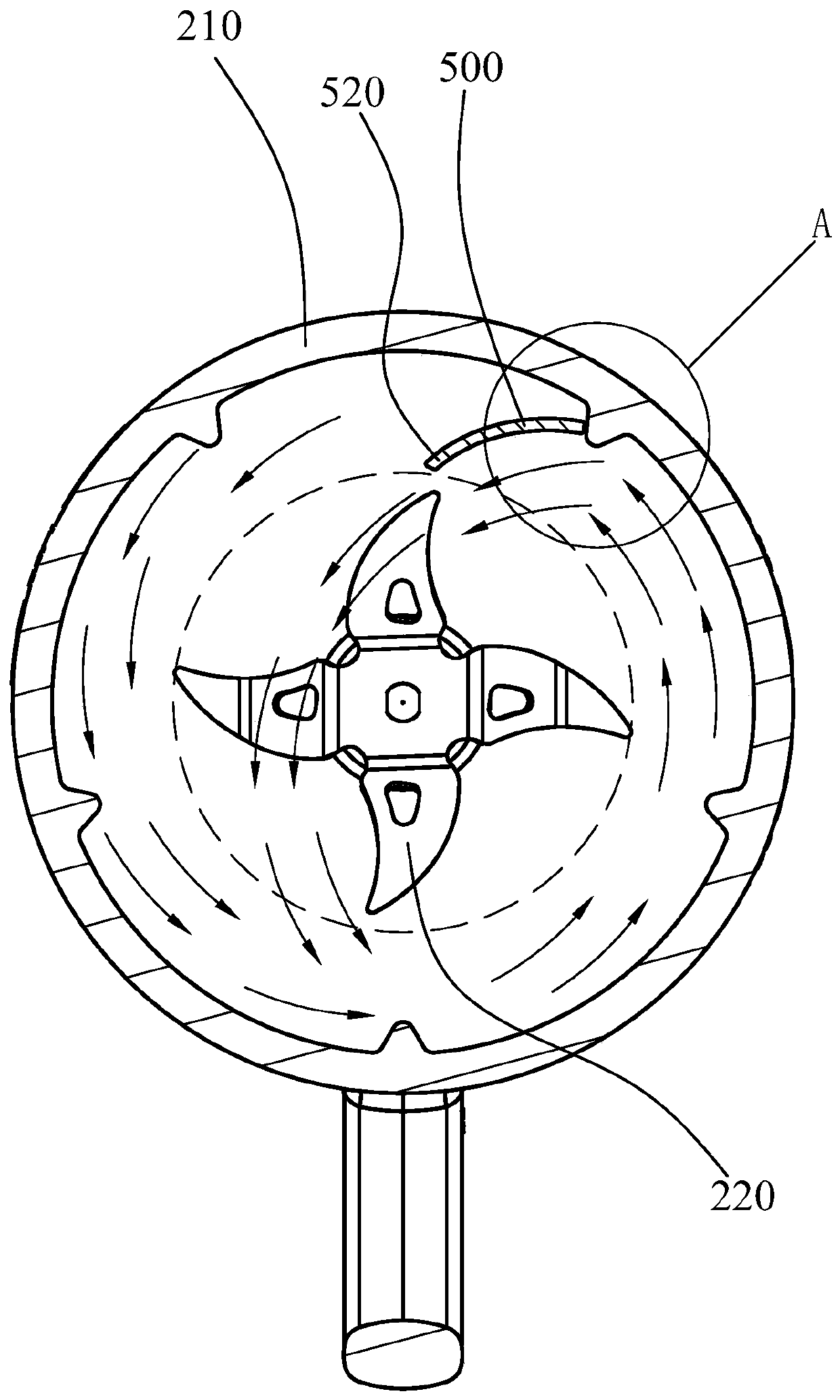
[0043] Such as Figures 1 to 7As shown, a food processing machine with good noise reduction effect includes a machine base 100, a cup body assembly 200 and a cup cover 300. A motor 110 is arranged inside the machine base 100, and the cup body assembly 200 is arranged on the machine base 100. The cup body The assembly 200 includes a cup body 210 and a crushing knife 220, the crushing knife 220 is arranged on the inner bottom of the cup body 210 and driven by the motor 110, the cup cover 300 is closed on the mouth of the cup body 210, and the inside The cup wall is provided with at least two spoiler ribs, and the spoiler ribs 211 are integrally formed on the inner cup wall of the cup body 210. The spoiler ribs 211 include a flow-facing surface 211a and a flow-back surface 211b. The top of the spoiler ribs The arc surface 211c is provided, and the root of the spoiler rib 211 is connected to the side wall of the cup body. The flow guide 500 in the cup body 210 is attached to the b...
Embodiment 2
[0065] Such as Figures 8 to 11 As shown, the difference between this embodiment and Embodiment 1 is that the feeding channel on the cup cover 300 is set eccentrically, the flow guide 500 is fixed on the feeding channel after passing through the feeding channel, and the lower end of the flow guide 500 extends Into the cup body 210 and attached to the backflow surface 211a of one of the spoiler ribs 211 to form an eccentric water flow.
[0066] In the prior art, the feeding channel is usually set at the center of the mixing cup, and the deflector needs to be bent and extended to the side wall of the cup body after passing through the feeding channel so as to be attached to the spoiler ribs to form a spoiler assembly, which requires The deflector has a large degree of bending and the bending path is long, which affects the manufacturability and strength of the deflector. It also makes it inconvenient for the deflector to pass through the deflector channel, which affects the user...
Embodiment 3
[0078] Such as Figure 12 , 13 As shown, the difference between the present embodiment and the first embodiment is that the deflector 500 is installed in the cup body 210 . Specifically, the deflector 500 includes a first annular portion 550, a second annular portion 560 and a deflector 570, the first annular portion 550 and the second annular portion 560 are arranged up and down, and the deflector 570 The two ends of the first annular portion 550 and the second annular portion 560 are respectively connected to form a flow guide.
[0079] Specifically, such as Figure 13 As shown, the contours of the first annular portion 550 and the second annular portion 560 are adapted to the inner wall contour of the cup body 210, and the outer sides of the first annular portion 550 and the second annular portion 560 are respectively provided with The gap 580 matched with the flow ribs can prevent the flow guide 500 from rotating under the impact of the liquid flow after it is installed...
PUM
 Abstract
Description
Claims
Application Information
 - R&D
- Intellectual Property
- Life Sciences
- Materials
- Tech Scout
- Unparalleled Data Quality
- Higher Quality Content
- 60% Fewer Hallucinations
Browse by: Latest US Patents, China's latest patents, Technical Efficacy Thesaurus, Application Domain, Technology Topic, Popular Technical Reports.
© 2025 PatSnap. All rights reserved.Legal|Privacy policy|Modern Slavery Act Transparency Statement|Sitemap|About US| Contact US: help@patsnap.com


