Fire extinguishing system and fire extinguishing method thereof

A fire extinguishing system and fire-fighting technology, which is applied in fire rescue and other fields, can solve the problem of inconvenient winding process, and achieve the effect of easy unwinding and winding

Active Publication Date: 2019-08-30
四川安泰信建设集团有限公司
View PDF8 Cites 14 Cited by
  • Summary
  • Abstract
  • Description
  • Claims
  • Application Information

AI Technical Summary

Problems solved by technology

[0004] When the fire hose is rewound by the above-mentioned correct method of rewinding the fire hose, a large space is required to fold the fire hose in half, and it is easy for

Method used


Image

  • Fire extinguishing system and fire extinguishing method thereof
  • Fire extinguishing system and fire extinguishing method thereof
  • Fire extinguishing system and fire extinguishing method thereof

Examples


Embodiment 1

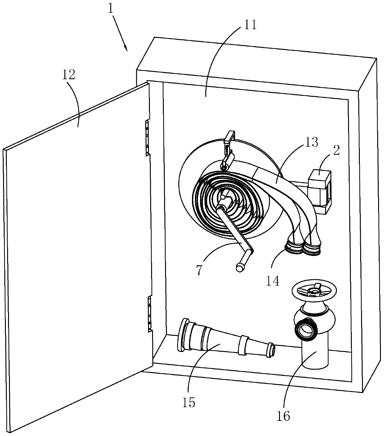
[0041] Such as figure 1 , 2 As shown, a fire extinguishing system includes a fire hydrant box 1, and the fire hydrant box 1 includes a box body 11, a door 12, a fire hose 13, joints 14 fixedly arranged at both ends of the fire hose 13, a fire hose 15 and a fire hose The bolt head 16 and the inner wall of the box body 11 are fixedly provided with a mounting seat 2, and the mounting seat 2 is hinged with a mounting arm 3 that can rotate in a horizontal plane.

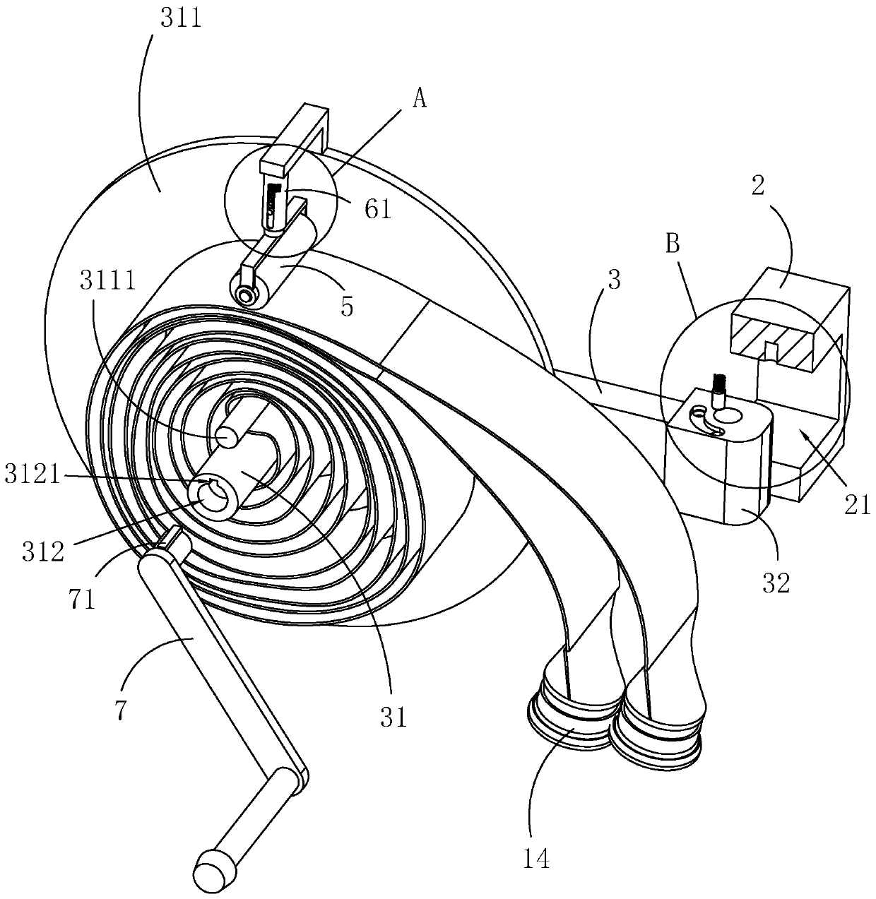
[0042] Such as figure 1 , 2 As shown, the end of the mounting arm 3 away from the mounting base 2 is rotated and provided with a winding roller 31 for winding the fire hose 13, the winding roller 31 is perpendicular to the mounting arm 3, and the winding roller 31 is fixed on the end close to the mounting arm 3 A limit plate 311 is provided, on which a fixed rod 3111 parallel to the take-up roller 31 is fixed, and on the limit plate 311 a pressing roller 5 parallel to the take-up roller 31 is rotatably arranged.

[00...

Embodiment 2

[0054] A fire extinguishing method, comprising the following steps: performing a fire extinguishing operation through a fire extinguishing system according to any one of claims 1-8;

[0055] S1, open the box door 12, turn the installation arm 3, make the installation arm 3 perpendicular to the box body 11, release the limitation of the abutment assembly on the pressure roller 5, and make the pressure roller 5 separate from the fire hose 13, so that the fire hose 13 can Pull out smoothly;

[0056] S2. Connect one joint 14 of the fire hose 13 with the fire hydrant head 16, and connect the other joint 14 with the fire hose 15, pull the fire hose 13, and pull the fire hose 15 to the fire place;

[0057] S3, open the valve on the fire hydrant head 16, you can spray water to extinguish the fire;

[0058] S4. After the fire extinguishing is completed, close the valve of the fire hydrant head 16, remove the fire hose 13 and the fire hose 15, fold the middle of the fire hose 13 in hal...


PUM


Abstract

The invention relates to a fire extinguishing system and a fire extinguishing method thereof, belongs to the technical field of fire control; the fire extinguishing system comprises a fire hydrant box; the fire hydrant box comprises a box body, a box door, a fire hose, joints fixedly arranged at the two ends of the fire hose, a fire water gun and a fire hydrant head; the inner wall of the box bodyis fixedly provided with an installation base; an installation arm is hinged with the installation base; the installation arm is rotationally provided with a winding roller; the winding roller is perpendicular to the installation arm; a fixing rod is fixedly arranged on a limiting disk; a compression roller parallel to the winding roller is rotationally arranged on the limiting disk; an abuttingassembly for driving the compression roller to abut against the fire hose on the winding roller is arranged on the limiting disk; and one end, away from the installation arm, of the winding roller isprovided with a rotating handle convenient to rotate the winding roller. During the using process, the box door is opened, and then the installation arm is rotated, so that the installation arm is perpendicular to the box boxy; the rotating handle is dismounted, the fire hose is taken down; the two joints of the fire hose are respectively connected with the fire water gun and the fire hydrant head, and the fire hose is dragged to a fire place to extinguish the fire.

Description

technical field [0001] The invention relates to the technical field of fire fighting, in particular to a fire extinguishing system and a fire extinguishing method thereof. Background technique [0002] Fire hydrant box is a kind of commonly used fire extinguishing equipment. In various buildings, one or several fire hydrant boxes will be installed on the walls of stairwells or corridors for fire and other emergency incidents. The fire hose inside the fire hydrant box is used for disaster relief and fire extinguishing, so as to reduce the loss of accidents, and the fire hose in the fire hydrant box should adopt the correct rolling method, so that the firefighters can quickly open the fire hose when using it. And it won't be discounted when you open it. [0003] The correct rolling method of the fire hose: the first step: stretch the fire hose flat; the second step: fold the fire hose in half once, and make the distance between the two interfaces at the two ends of the fire h...

Claims


Application Information

Patent Timeline
IPC IPC(8): A62C33/04A62C35/20
CPCA62C33/04A62C35/20
Inventor 吴增富周肖文伍玉霞
Owner 四川安泰信建设集团有限公司
Why Eureka
Try Eureka