Split side mold and wheel hub mold applied thereby

A split-type, side-mold technology, applied in the field of wheel hub molds, can solve problems such as delays in production progress, exposure of air holes, and leakage of metal solution, and achieve the effects of compact and stable overall structure, optimized and reasonable layout, and improved manufacturing efficiency.

Pending Publication Date: 2019-08-30
FOSHAN NANHAI SUPERBAND MOLD
View PDF1 Cites 2 Cited by
  • Summary
  • Abstract
  • Description
  • Claims
  • Application Information

AI Technical Summary

Problems solved by technology

[0003] The new side mold in the patent 200720025750.X can effectively solve the problem of the gradient change of the mold wall thickness and balance the heat absorption and heat dissipation capacity of the mold, and improve the product quality of the wheel hub
However, it still cannot solve the problem of air holes exposed on the cavity surface after plasticizing the side mold, and it is necessary to connect each plate body one by one, the structure is loose, not only inconvenient to disassemble, but also difficult to give the inner side The precise and uniform positioning of the templates is very easy to cause the inner templates on the adjacent side molds to not fit together tightly in specific applications, forming an obvious gap between them and allowing the molten metal flowing in the cavity to leak out. In the industry, it is commonly known as "running aluminum". This will not only form obvious flash on the wheel hub blank and affect the quality of the finished wheel hub, but also need to disassemble each plate body one by one for cleaning, which greatly delays the production schedule.

Method used


Image

  • Split side mold and wheel hub mold applied thereby
  • Split side mold and wheel hub mold applied thereby
  • Split side mold and wheel hub mold applied thereby

Examples


Embodiment Construction

[0025] The structure of the split side form applying the technical solution of the present invention and the structure of the wheel hub mold applied thereto will be further described below in conjunction with the accompanying drawings.

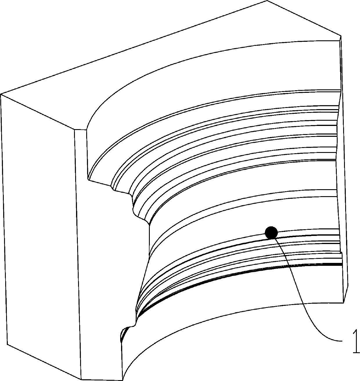
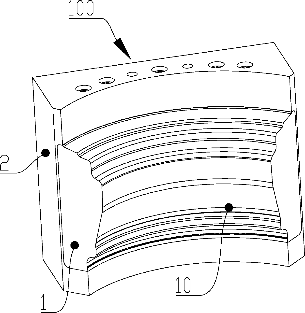
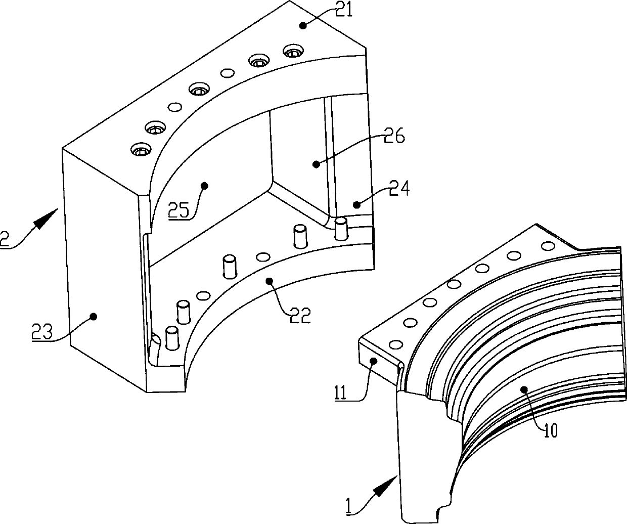
[0026] Such as Figure 2 to Figure 5 Shown is a schematic structural view of a split side form 100 , which includes an integrally formed side form main frame body 2 . The main frame body 2 of the side mold belongs to a casting, and includes a top side wall 21 and a bottom side wall 22 separated from the upper and lower sides, and a left side wall integrally formed between the top side wall 21 and the bottom side wall 22. The side wall 23 and the right side wall 24 form a back chamber 25 with a front opening 26 between the top side wall 21 , the bottom side wall 22 , the left side wall 23 and the right side wall 24 . Wherein, the side mold main frame body 2 is one of the split body of the split side mold 100, which adopts an integrally formed ...


PUM


Abstract

The invention relates to a split side mold and a wheel hub mold applied thereby. The split type side mold is characterized by comprising an integrally formed side mold main rack body. The side mold main rack body comprises a top side wall and a bottom side wall separately arranged up and down and a left side wall and a right side wall integrally formed between the top side wall and the bottom sidewall. Back cavities with front openings are formed among the top side wall, the bottom side wall, the left side wall and the right side wall. The split side mold also comprises a front side module which seals the front openings. A split type structure is arranged between he front side module and the side mold main rack body. The front side module is a forged part and is used for encircling a workpiece forming cavity. As the side mold main rack body is of the integrally formed structure, the integral structure of the side mold main rack body is compact and stable and can position the front side module precisely, uniformly and stably, so that the front side modules of adjacent side molds in application can be matched tightly, so that the phenomenon of aluminum slop out of mold is avoided.

Description

technical field [0001] The invention relates to a split side mold, and also relates to a wheel hub mold using the split side mold. Background technique [0002] Low-pressure casting is currently the main forming process for automotive aluminum alloy wheels. As one of the key mold parts, the side mold is mainly used to form the rim area of ​​the wheel hub. At present, the more common side molds generally adopt an integrated side mold structure, such as figure 1 As shown, the side mold includes a cavity surface 1 for enclosing the cavity. This one-piece side form is usually prepared by sand core casting process, except for the back cavity area of ​​the side form, all other parts are left with a machining allowance of 10-15 mm. Since large and small air holes distributed in different regions will be formed in the side mold casting blank during the casting process, after machining the side mold cavity surface of the side mold casting blank, part of the air hole defects are di...

Claims


Application Information

Patent Timeline
IPC IPC(8): B22D18/04
CPCB22D18/04
Inventor 简伟文杨乾文谢少平符强
Owner FOSHAN NANHAI SUPERBAND MOLD
Why Eureka
Try Eureka