Eureka AIR delivers breakthrough ideas for toughest innovation challenges, trusted by R&D personnel around the world.

Immersed nozzle of H-shaped leakproof steel

An immersion and nozzle technology, applied in casting melt containers, metal processing equipment, casting equipment, etc., can solve the problems of continuous casting and pouring, accumulation of inclusions, leakage of casting billets, etc., to reduce the residence time, The effect of eliminating gaps and stabilizing the flow of molten steel

Pending Publication Date: 2019-08-30
SHANXI TONGCAI IND & TRADE
View PDF0 Cites 2 Cited by
  • Summary
  • Abstract
  • Description
  • Claims
  • Application Information

AI Technical Summary

Problems solved by technology

At present, the inner wall of the submerged nozzle is straight up and down cylindrical, and the inner wall is easy to cause inclusions to accumulate during the pouring process, resulting in the flow blocking phenomenon of the nozzle, so that the continuous casting cannot be carried out smoothly. The submerged nozzle with steel tapping on both sides flows into crystal The molten steel of the caster directly scours the surrounding solidified slab shell, which is the main cause of the slab leaking
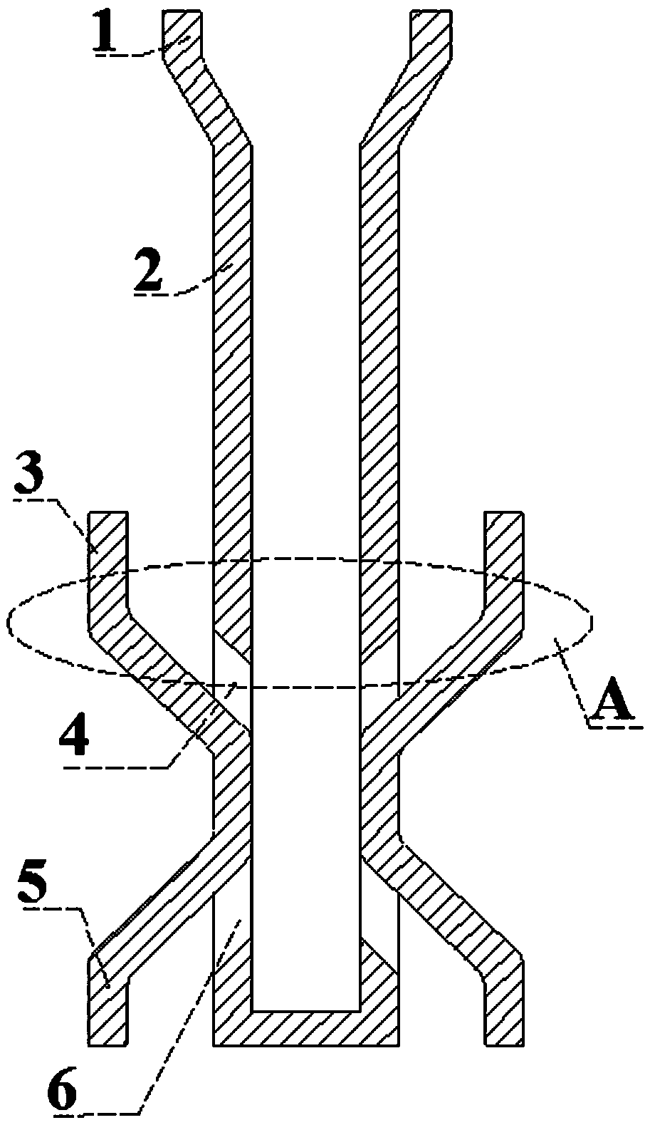
[0005] In order to solve the problem of steel breakout caused by tapping the steel on both sides of the existing submerged nozzle to directly scour the solidified billet shell, the present invention develops an H-shaped leak-proof steel submerged nozzle

Method used


Image

  • Immersed nozzle of H-shaped leakproof steel
  • Immersed nozzle of H-shaped leakproof steel
  • Immersed nozzle of H-shaped leakproof steel

Examples


Embodiment 1

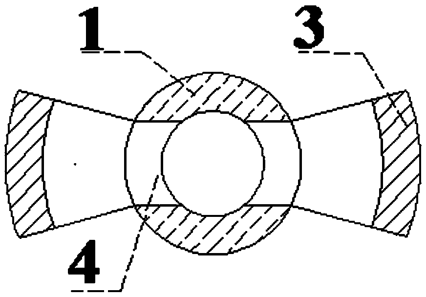
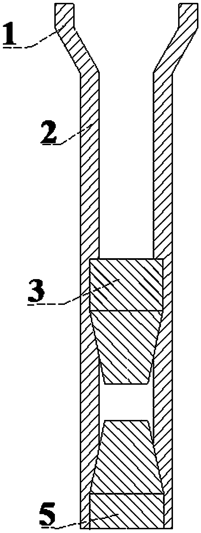
[0027] Such as figure 1 The shown H-shaped leak-proof steel immersion nozzle includes a nozzle main body 2, an upward dam 3, an upwardly inclined steel outlet 4, a downward dam 5, and a downwardly inclined steel outlet 6; the nozzle body The upper part of 2 is the bowl mouth structure 1, the lower part is a hollow cylindrical structure with a smooth inner cavity, and the bottom end is a closed structure; the upper part of the bowl mouth structure 1 is a large-aperture hollow cylinder, and the lower end is a tapered structure. The bottom of the structure is consistent with the inner diameter of the hollow cylindrical structure at the lower part of the nozzle body; the hollow cylindrical structure of the nozzle body 2 is symmetrically provided with a pair of upwardly inclined steel outlets 4 and a hollow cylinder at the lower part of the upwardly inclined steel outlet 4 A pair of upward dams 3 are arranged symmetrically in structure, a pair of downward dams 5 are symmetrically arr...

Embodiment 2

[0030] Such as Figure 4 The shown H-shaped leak-proof steel immersion nozzle includes a nozzle main body 2, an upward dam 3, an upwardly inclined steel outlet 4, a downward dam 5, and a downwardly inclined steel outlet 6; the nozzle body The upper part of 2 is the bowl mouth structure 1, the lower part is a hollow cylindrical structure with a smooth inner cavity, and the bottom end is a concave spherical closed structure; wherein the bowl mouth structure 1 is a conical structure, and the bottom of the conical structure is connected to the hollow cylindrical structure, The inner diameter of the bottom of the conical structure is the same as the inner diameter of the hollow cylindrical structure; the middle and lower parts of the hollow cylindrical structure of the nozzle body 2 are symmetrically provided with a pair of upwardly inclined steel outlets 4, and the hollow at the lower part of the upwardly inclined steel outlet 4 A pair of upward dams 3 are symmetrically arranged on...


PUM


Abstract

The invention discloses an immersed nozzle of H-shaped leakproof steel and belongs to the technical field of steel continuous casting. The immersed nozzle of the H-shaped leakproof steel comprises a nozzle main body, upward blocking dams, upward inclined steel outlets, downward blocking dams and downward inclined steel outlets, the upper part of the nozzle main body is of a bowl opening structure,the lower part of the nozzle main body is of a hollow cylindrical structure with a smooth inner cavity, and the bottom end of the nozzle main body is of a closed structure; the upper part of the bowlopening structure is in a large-aperture hollow cylindrical shape, and the lower end of the bowl opening structure is of a conical structure; the middle lower part of the hollow cylindrical structureof the nozzle main body is symmetrically provided with the pair of upward inclined steel outlets, the lower parts of the upward inclined steel outlets are symmetrically provided with the pair of upward blocking dams, the lower parts of the upward blocking dams are symmetrically provided with the pair of downward blocking dams, and the lower parts of the downward blocking dams are symmetrically provided with the pair of downward inclined steel outlets. Direct flushing of molten steel on a solidified shell can be reduced, occurrence of steel leakage is avoided, the production efficiency is improved, and the production cost is reduced.

Description

Technical field [0001] The invention belongs to the technical field of steel continuous casting, and mainly relates to an H-shaped leak-proof steel immersion nozzle. Background technique [0002] Breakout refers to the phenomenon that molten steel flows out of the solidified blank shell due to too fast drawing speed, uneven heat transfer of the solidified shell, mold flux entrapment or other external forces scouring the solidified shell during the initial stage of continuous casting or during the pouring process. Breakout is one of the malignant accidents in the continuous casting production process. The lighter ones cause a decrease in the metal recovery rate, and the more serious ones burn out the secondary cooling device, interrupt the continuous casting and endanger the lives of workers. [0003] There are many forms of breakout, mainly including open cast breakout, suspension breakout, crack breakout, slag breakout, cut breakout and bonded breakout, etc. The main influencing ...

Claims


Application Information

Patent Timeline
Patent Type & Authority Applications(China)
IPC IPC(8): B22D41/50
CPCB22D41/50
Inventor 齐治畔朱嘉刘鹏
Owner SHANXI TONGCAI IND & TRADE
Why Eureka
Eureka Blog
Learn More