A far -hearted lens

A telecentric lens and lens technology, applied in optical components, instruments, optics, etc., can solve the problems of slow shooting rhythm, low tolerance sensitivity, and low light source coupling efficiency, so as to improve image brightness, reduce exposure time, and improve detection efficiency effect

Active Publication Date: 2021-01-12
FREESENSE IMAGE TECH
View PDF12 Cites 0 Cited by
  • Summary
  • Abstract
  • Description
  • Claims
  • Application Information

AI Technical Summary

Problems solved by technology

[0002] In ITO micro-area detection, the current detection lenses are mostly object-space telecentric lenses, and their numerical apertures are mostly 0.112, 0.14, etc. The small numerical apertures lead to a low ability of the lens to collect reflected light from the object, and the camera of the detection equipment The exposure time setting is relatively long, and the resolution of the object space is relatively low, that is, the numerical aperture of the object space is small, the coupling efficiency of the light source is low, the image brightness is low, and the shooting pace is slow
[0003] For example, the application number is: 201910064847.9, the name is a kind of telecentric lens, which discloses a first lens G1 with positive refractive power and biconvex structure, which is arranged sequentially from the object end to the image plane, and has a negative refractive power and a meniscus structure. The second lens G2 with positive refractive power and biconvex structure third lens G3, the fourth lens G4 with negative refractive power and biconcave structure, prism, the fifth lens G5 with positive refractive power, and the fifth lens G5 with positive refractive power The sixth lens G6 with a double-concave structure and high magnification achieves high resolution and low tolerance sensitivity at high magnifications. While having excellent imaging quality, the lens is easy to produce, but there is still no solution The problem of the small numerical aperture of the existing lens on the object side, and how to solve the problem of low coupling efficiency of the lens and light source and reduce the exposure time of the camera to improve the detection efficiency of the machine vision machine

Method used


Image

  • A far -hearted lens
  • A far -hearted lens
  • A far -hearted lens

Examples


Embodiment Construction

[0019] The following will clearly and completely describe the technical solutions in the embodiments of the present invention with reference to the accompanying drawings in the embodiments of the present invention. Obviously, the described embodiments are only some, not all, embodiments of the present invention. Based on the embodiments of the present invention, all other embodiments obtained by persons of ordinary skill in the art without making creative efforts belong to the protection scope of the present invention.

[0020] In the description of the present invention, it should be noted that the terms "upper", "lower", "inner", "outer", "front end", "rear end", "both ends", "one end", "another end" The orientation or positional relationship indicated by etc. is based on the orientation or positional relationship shown in the drawings, and is only for the convenience of describing the present invention and simplifying the description, rather than indicating or implying that ...


PUM


Abstract

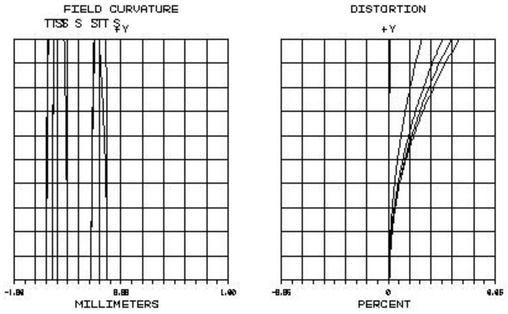
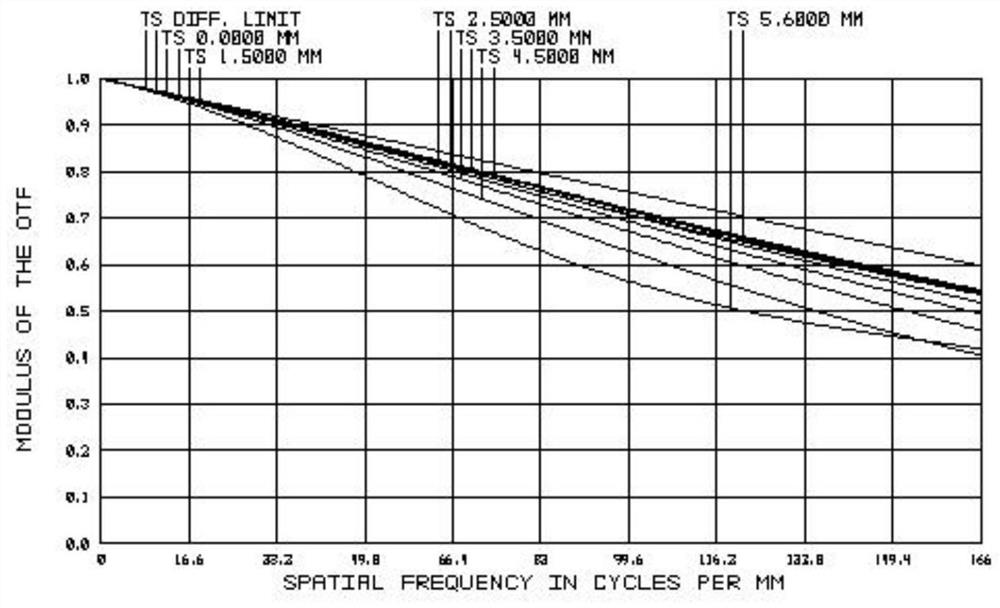
The invention discloses a telecentric lens set. The telecentric lens set comprises a first lens, a second lens, a gluing prism, a third lens, a fourth lens, a fifth lens, a diaphragm, a sixth lens, aseventh lens, an eighth lens and a ninth lens, all of which are sequentially arranged from an object space to an image space, wherein the first lens has positive focal power and is of a double-convexstructure, the second lens has positive focal power and is of a crescent structure, the third lens has positive focal power and is of a crescent structure, the fourth lens has positive focal power andis of a double-convex structure, the fifth lens has negative focal power and is of a double-concave structure, the sixth lens has positive focal power and is of a double-convex structure, the seventhlens has negative focal power and is of a double-concave structure, the eighth lens has positive focal power and is of a double-convex structure, and the ninth lens has negative focal power and is ofa double-concave structure. According to the telecentric lens set, through combination of the corresponding optical elements, high-resolution, large-view-field and high-luminance imaging with four-times magnifying power, a 0.18 numerical aperture, a 65mm object-space working distance and a 11mm image-space image circle is realized.

Description

technical field [0001] The invention relates to the field of machine vision telecentric lenses, in particular to a telecentric lens. Background technique [0002] In ITO micro-area detection, the current detection lenses are mostly object-space telecentric lenses, and their numerical apertures are mostly 0.112, 0.14, etc. The small numerical apertures lead to a low ability of the lens to collect reflected light from the object, and the camera of the detection equipment The exposure time setting is relatively long, and the object space resolution is relatively low, that is, the object space numerical aperture is small, the light source coupling efficiency is low, the image brightness is low, and the shooting pace is slow. [0003] For example, the application number is: 201910064847.9, the name is a kind of telecentric lens, which discloses a first lens G1 with positive refractive power and biconvex structure, which is arranged sequentially from the object end to the image pl...

Claims


Application Information

Patent Timeline
Patent Type & Authority Patents(China)
IPC IPC(8): G02B13/22
CPCG02B13/22
Inventor 景磊
Owner FREESENSE IMAGE TECH
Why Eureka
Try Eureka