Method for preparing perforated structure optical cavity F-P optical fiber sensor based on gold-gold bonding

A technology of optical fiber sensor and optical cavity, which is applied in the direction of using optical devices to transmit sensing components, metal material coating technology, vacuum evaporation plating, etc., can solve the problem of low production efficiency of F-P optical fiber sensors, the inability to promote large-scale utilization, and bonding Process requirements are very high, to achieve the effect of ensuring alignment, high controllability, and no chipping

Active Publication Date: 2019-07-26
SHANDONG UNIV
View PDF12 Cites 0 Cited by
  • Summary
  • Abstract
  • Description
  • Claims
  • Application Information

AI Technical Summary

Problems solved by technology

In addition, at present, the existing F-P fiber optic sensor is usually formed by adhering the borosilicate glass side of the bonded sensor head to the end face of the fiber pigtail through glue, but due to the bonding alignment, fiber-UV glue -Interference between the borosilicate glass interface and the internal transmission loss of the borosilicate glass substrate makes the noise interference in the system larger, and the requirements for the bonding process are very high, and the production efficiency of the F-P optical fiber sensor is low, which cannot be widely promoted use

Method used


Image

  • Method for preparing perforated structure optical cavity F-P optical fiber sensor based on gold-gold bonding
  • Method for preparing perforated structure optical cavity F-P optical fiber sensor based on gold-gold bonding
  • Method for preparing perforated structure optical cavity F-P optical fiber sensor based on gold-gold bonding

Examples


Embodiment 1

[0047] A method for preparing a perforated structure optical cavity F-P fiber sensor based on gold-gold bonding,

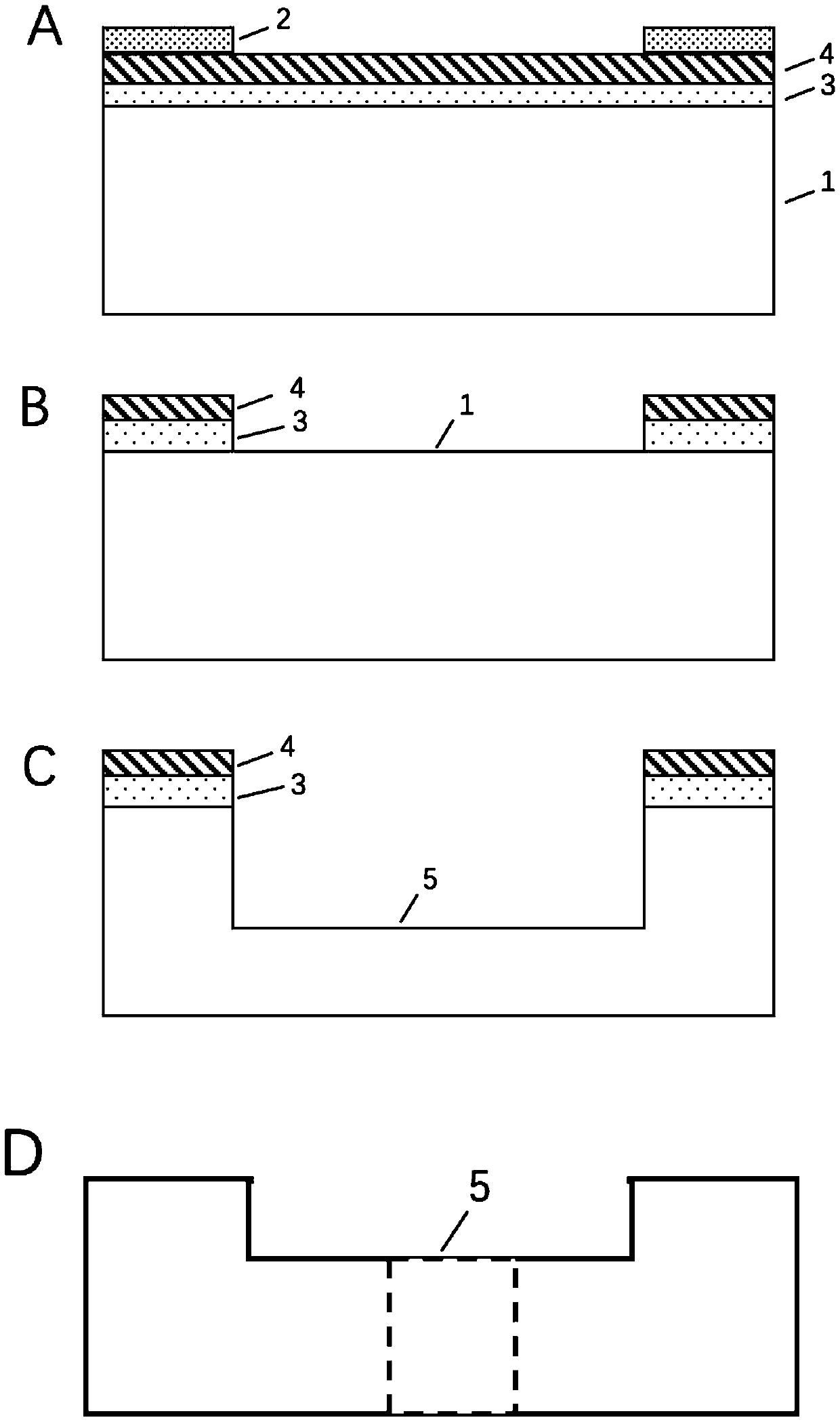
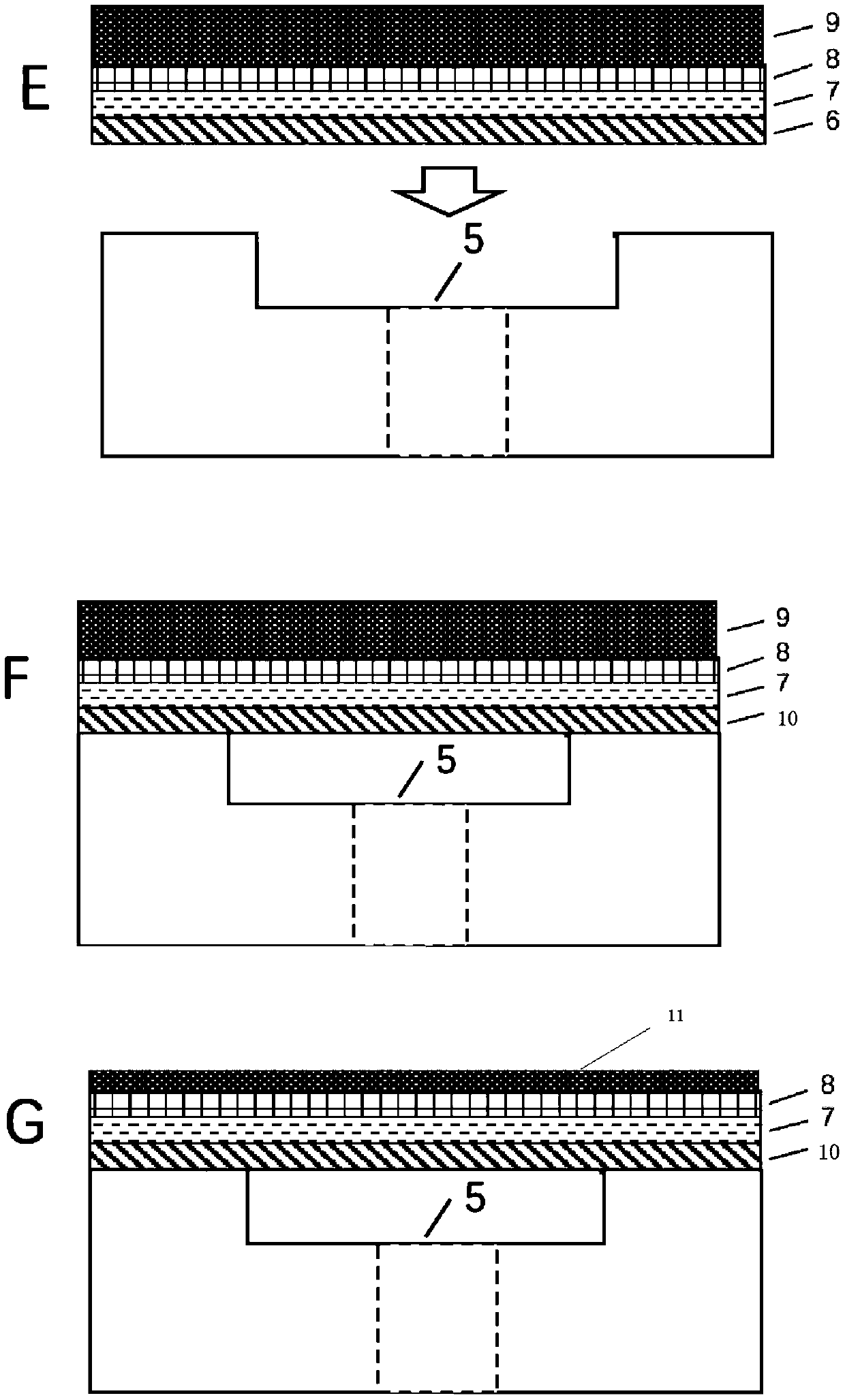
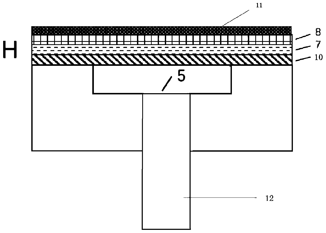
[0048] Ni / Au and Ti / Pt / Au thin films were prepared by sputtering on borosilicate glass and silicon wafer respectively, and a patterned Ni / Au mask was formed on borosilicate glass by wet etching. The optical cavity is etched on the borosilicate glass, and the laser drilling technology is used to process the penetrating hole on the borosilicate glass substrate and then bonded with gold and gold to complete the fabrication of the optical cavity. The specific steps are as follows: figure 1 Shown:

[0049] (1) successively sputtering thickness is the Ni film 3 of 200nm and the Au film 4 of 600nm on the surface of borosilicate glass 1, forms Ni / Au alloy film; One side of borosilicate glass 1 sputtering metal film is thrown with a homogenizer Layer photoresist positive resist (AZ1500) 2, then align the photoresist plate for exposure and development, and put it into the ...

Embodiment 2

[0058] A method for preparing a perforated structure optical cavity F-P optical fiber sensor based on gold-gold bonding as described in Example 1, the difference is:

[0059] The laser drilling is femtosecond laser drilling, the femtosecond laser wavelength is 800nm, the pulse width is 120fs, the repetition frequency is 250KHz, and the maximum pulse energy is 6μJ; the diameter of the penetrating hole is 126-130 microns.

experiment example

[0062] Experimental example, spectrum experiment

[0063] Build a test light path, such as image 3 As shown, it includes a data processing terminal 10 , a spectrometer 11 , an output light source 12 , a light circulator 13 , and a sensor 14 . The output light source 12 is connected to the fiber optic circulator 13 , the fiber optic circulator 13 is connected to the sensor 14 , the spectrometer 11 is connected to the fiber optic circulator 13 , and the data processing terminal 10 is connected to the spectrometer 11 . The sensors 14 are optical fiber sensors manufactured in Example 1 and Comparative Example 1, respectively.

[0064] In the experiment, the output light source 12 adopts 850nm wavelength LED, the spectrometer 11 adopts Ocean Optics HR4000 fiber optic spectrometer, and the data processing terminal 10 is a computer processor. The return interference spectrum collected by the spectrometer is as follows: Figure 4 , Figure 5 as shown, Figure 4 In order to compa...


PUM

PropertyMeasurementUnit
thicknessaaaaaaaaaa
thicknessaaaaaaaaaa
thicknessaaaaaaaaaa

Abstract

The invention relates to a method for preparing a perforated structure optical cavity F-P optical fiber sensor based on gold-gold bonding. According to the method, a femtosecond laser drilling technology is adopted, laser drilling is conducted on a borosilicate glass substrate to enable an optical fiber to penetrate directly into the borosilicate glass substrate, so that fiber end face is considered as a first reflecting surface which forms an optical cavity, and then the perforated structure optical cavity F-P optical fiber sensor is manufactured through the gold-gold bonding. According to the method, the reflection loss and noise of a fiber-UV glue-borosilicate glass interface in an existing adhesion method are eliminated, and at the same time, additional operation of optical fiber collimation is not needed because a through hole is perpendicular to the bottom of the optical cavity. Technological operation that the optical fiber is coupled with sensor heads is simplified while coupling efficiency is improved, the signal-to-noise ratio of return signals is enhanced, the gold-gold hot-pressing bonding temperature is low and the controllability of the bonding is high.

Description

technical field [0001] The invention relates to a method for preparing a perforated structure optical cavity F-P fiber sensor based on gold-gold bonding, and belongs to the technical field of micro-optoelectronic device production. Background technique [0002] Optical fiber sensing technology began in 1977 and developed rapidly with the development of optical fiber communication technology. Optical fiber sensing technology is an important symbol to measure the degree of informatization of a country. So far, optical fiber sensing technology has been widely used in military, national defense, aerospace, industrial and mining enterprises, energy and environmental protection, industrial control, medicine and health, metrology and testing, construction, household appliances and other fields, and has a broad market. There are hundreds of optical fiber sensing technologies in the world, and physical quantities such as temperature, pressure, flow, displacement, vibration, rotation,...

Claims


Application Information

Patent Timeline
Patent Type & Authority Applications(China)
IPC IPC(8): G01D5/353C23C14/34C23C14/16C03C15/00
CPCC03C15/00C23C14/165C23C14/34G01D5/353
Inventor 徐现刚王荣堃
Owner SHANDONG UNIV
Why Eureka
Try Eureka