A coupling lens system

A technology of coupling lens and transmission optical fiber, which is applied in the field of lighting, can solve the problems of large transmission loss of plastic optical fiber, easy melting of plastic optical fiber, high single-point energy optical fiber, etc., so as to improve the reliability of optical fiber, facilitate processing and reduce coupling efficiency Effect

Active Publication Date: 2020-12-11
ZHEJIANG LIGHTTOWER SAFETY TECH CO LTD
View PDF1 Cites 0 Cited by
  • Summary
  • Abstract
  • Description
  • Claims
  • Application Information

AI Technical Summary

Problems solved by technology

To meet the luminous characteristics of LED light sources and improve the coupling efficiency, the diameter of the fiber needs to be increased, and the cost of the fiber will increase exponentially with the increase in diameter
[0005] 2. The surface of the general coupling lens is mostly spherical. The spherical lens can converge light rays from different angles into a focal point, so that the energy can be concentrated on the optical fiber at a single point. If the energy at a single point is too high, the optical fiber is easy to burn.
In addition, the temperature resistance of the material of plastic optical fiber is relatively poor, and plastic optical fiber is more likely to be melted
[0006] 3. It is difficult to deal with the end face of plastic optical fiber. Once the end face angle is deviated or the surface smoothness is not enough, it will cause a large amount of fiber scattering on the end face, and the coupling efficiency is low.
[0007] 4. The transmission loss of plastic optical fiber is too large. The imported optical fiber is about 150dB / km, while the domestic optical fiber is about 250dB / km. Light in the optical fiber cannot be transmitted at short distances with high transmission efficiency and low cost, nor can it be transmitted at long distances. Not to mention satisfying both high transmission efficiency and low cost during long-distance transmission
However, the lens coupling system uses a high-power semiconductor laser fiber coupling system, which generally uses a spherical lens, which does not solve the problem of single-point energy and high-flammable optical fibers caused by spherical lenses converging light sources from various angles at one focus.

Method used


Image

  • A coupling lens system
  • A coupling lens system
  • A coupling lens system

Examples


Embodiment Construction

[0028] The following are specific embodiments of the present invention and in conjunction with the accompanying drawings, the technical solutions of the present invention are further described, but the present invention is not limited to these embodiments.

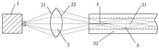
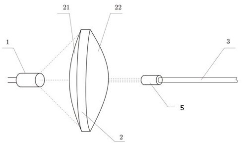
[0029] figure 1 A coupling lens system of the present invention is shown, and the system includes a laser light source 1 , a coupling lens 2 , and a transmission fiber 3 . The coupling lens 2 is arranged between the laser light source 1 and the transmission fiber 3 . The laser light source 1, the coupling lens 2 and the transmission fiber 3 are connected through an optical path. Light rays of different angles emitted by the laser light source are coupled into the transmission fiber 3 through the coupling lens 2 . In order to improve the coupling efficiency and prevent the light from escaping so that the light enters the transmission fiber 3 and is transmitted in the form of total reflection, the light needs to be coupled...


PUM

PropertyMeasurementUnit
diameteraaaaaaaaaa

Abstract

The invention relates to a coupling lens system, and belongs to the technical field of lighting. The coupling lens system comprises a laser light source, a coupling lens and a transmission optical fiber, wherein the coupling lens is arranged between the laser light source and the transmission optical fiber; at least one of a light incoming end and a light outgoing end of the coupling lens has a free-form surface, when the light incoming end or the light outgoing end has a free-form surface and has at least one free-form surface, light emitted by the laser light source at different angles is coupled by the coupling lens, gets into the transmission optical fiber and is converged into a focal line at the central axis of a fiber core. The coupling lens system is applicable to high-power laserlighting, and solves a problem of low coupling efficiency caused by light emitting characteristics of an LED light source; and the light emitted by the light source is coupled into the optical fiber in a mode of the uniform focal line by using the coupling lens with the free-form surface structure, thereby avoiding the fusing caused by excessively high single-point energy in the optical fiber. Inaddition, the system is applicable to short-distance and even long-distance transmission with low cost and high transmission efficiency.

Description

technical field [0001] The invention relates to the technical field of lighting, in particular to a coupling lens system for lighting. Background technique [0002] At present, optical fiber communication technology has basically matured in the field of communication technology, and the application of optical fiber light guide to lighting is a new development direction of optical fiber light guide technology. Fiber-optic light-guiding lighting is a light-guiding lighting method with photoelectric separation. There is no electrical equipment at the output end of fiber-optic light-guiding lighting, so it is also a safe light source in places with fire hazards and explosive gases. Existing fiber optic light guide lighting is widely used in some low-power decorative lighting, signal lights and endoscopes, but there are still many difficulties in the field of high-power lighting that make it difficult to promote on a large scale. [0003] Existing coupling systems used in light ...

Claims


Application Information

Patent Timeline
Patent Type & Authority Patents(China)
IPC IPC(8): G02B6/26G02B6/32
CPCG02B6/262G02B6/32
Inventor 张航刘锐陆建东马佩服戚蓉蓉符建陈利春韩薇
Owner ZHEJIANG LIGHTTOWER SAFETY TECH CO LTD
Why Eureka
Try Eureka