A multimode fiber coupling system

A technology of multi-mode optical fiber and coupling system, applied in the field of lighting, can solve the problems of large optical fiber coupling loss, enlarged optical fiber diameter, easy burning and melting of optical fiber, etc.

Active Publication Date: 2020-10-30
ZHEJIANG LIGHTTOWER SAFETY TECH CO LTD
View PDF1 Cites 0 Cited by
  • Summary
  • Abstract
  • Description
  • Claims
  • Application Information

AI Technical Summary

Problems solved by technology

To meet the luminous characteristics of LED light sources and improve the coupling efficiency, the diameter of the fiber needs to be increased, and the cost of the fiber will increase exponentially with the increase in diameter
[0005] 2. The surface of the general coupling lens is mostly spherical. The spherical lens can converge light rays from different angles into a focal point, so that the energy can be concentrated on the optical fiber at a single point. If the energy at a single point is too high, the optical fiber is easy to burn.
In addition, the temperature resistance of the material of plastic optical fiber is relatively poor, and plastic optical fiber is more likely to be melted
[0006] 3. It is difficult to deal with the end face of plastic optical fiber. Once the end face angle is deviated or the surface smoothness is not enough, it will cause a large amount of fiber scattering on the end face, and the coupling efficiency is low.
[0007] 4. The transmission loss of plastic optical fiber is too large. Imported optical fiber is about 150Db / km, while domestic optical fiber is about 250Db / km. Light in optical fiber cannot be transmitted at short distances with high transmission efficiency and low cost, nor can it be transmitted at long distances. Not to mention satisfying both high transmission efficiency and low cost during long-distance transmission
Although the system uses blue light LD to solve the problems caused by the light emitting characteristics of LED light sources, the system still has the following problems: First, the lens used in the system uses a spherical mirror and a traditional convex lens, which has higher requirements on the divergence angle of the semiconductor laser. The special-shaped laser light source needs to increase the lens to achieve the desired effect, so it can only be used for the laser diode that has been packaged and collimated once; and the laser diode that has been packaged and collimated has the defect of low photoelectric conversion efficiency. ; In addition, the light is converged into a focal point by the spherical mirror, which leads to uneven energy dispersion on the fiber and reduces the power limit of fiber coupling transmission
Secondly, the system requires extremely high alignment accuracy of the light source, lens, and fiber optic axis, and the packaging cost is high
Then, the optical fiber used in the system has a large diameter, high optical fiber cost, and high engineering construction requirements; and the power-off coupling loss of the optical fiber is relatively large. If there are multiple breakpoints in the line, the entire line needs to be re-laid, and the maintenance cost is high.

Method used


Image

  • A multimode fiber coupling system
  • A multimode fiber coupling system
  • A multimode fiber coupling system

Examples


example 1

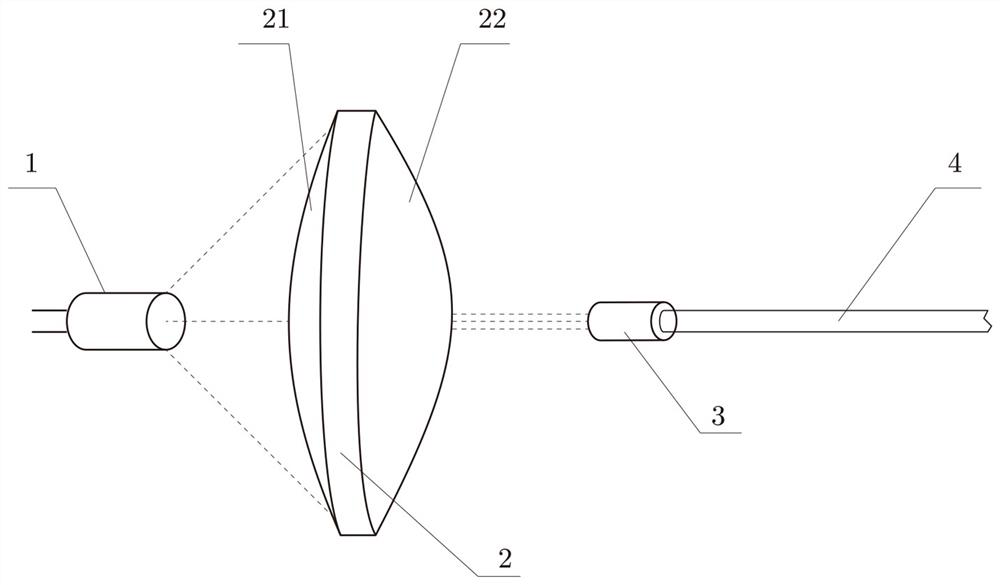
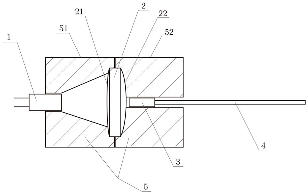
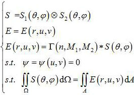
[0043] Example 1: The laser light source is a semiconductor laser, the laser light source 1 emits a special-shaped light beam, the beam is diffused in the horizontal axis direction, and the beam is converged in the vertical axis direction. The multimode optical fiber 4 is a multimode optical fiber with a core diameter of 62.5 μm. The multimode fiber collimator 3 adopts a C-lens fiber collimator. The design method combining ODE and SMS in the non-imaging design method is used to obtain two single-dimensional optical surface characteristic curves at the light entrance end according to the light exiting edge rays in the horizontal and vertical axis directions of the light source, and then combine them into the incoming light by tensor product. End free-form surface 21 . Using the same method, two single-dimensional optical surface characteristic curves of the light-emitting end are obtained according to the light-emitting edge rays in the horizontal and vertical axis directions ...

example 2

[0044] Example 2: The laser light source is a semiconductor laser, the laser light source 1 emits a special-shaped light beam, the beam in the horizontal axis direction is diffused, and the beam in the vertical axis direction is converged. The multimode optical fiber 4 is a multimode optical fiber with a core diameter of 62.5 μm. Optical fiber collimator 3 adopts G-lens optical fiber collimator.

[0045] The design method combining ODE and SMS in the non-imaging design method is used to obtain two single-dimensional optical surface characteristic curves at the light entrance end according to the light exiting edge rays in the horizontal and vertical axis directions of the light source, and then combine them into the incoming light by tensor product. End free-form surface 21 . Using the same method, two single-dimensional optical surface characteristic curves of the light-emitting end are obtained according to the light-emitting edge rays in the horizontal and vertical axis di...


PUM

PropertyMeasurementUnit
diameteraaaaaaaaaa

Abstract

A multi-mode fiber coupling system relates to the technical field of lighting technology. They system comprises a laser light source, a coupling lens, and a multi-mode optical fiber; wherein the coupling lens is disposed between the laser light source and the multi-mode optical fiber, and the end of the multi-mode optical fiber connected to the coupling lens is provided with a fiber collimator; atleast one of light incident end and light exit end of the coupling lens has free curved surfaces, and the light incident end or the light exit end that has the free curved surfaces also has at leastone free curved surface, so that different angles of light emitted by the laser light source is coupled into the fiber collimator of the multi-mode fiber through the coupling lens; the light enteringthe fiber collimator is coupled into the multi-mode fiber and converges into a focal line at the central axis of a fiber core. The system is suitable for high-power laser illumination for long-distance transmission, and utilizes the fiber collimator of the coupling lens and the multi-mode fiber to improve power upper limit of fiber coupling transmission, and solves the problems of high requirements of alignment precision, high packaging cost, and low coupling efficiency.

Description

technical field [0001] The invention relates to the technical field of lighting, in particular to a multimode optical fiber coupling system for lighting. Background technique [0002] At present, optical fiber communication technology has basically matured in the field of communication technology, and the application of optical fiber light guide to lighting is a new development direction of optical fiber light guide technology. Fiber-optic light-guiding lighting is a light-guiding lighting method with photoelectric separation. There is no electrical equipment at the output end of fiber-optic light-guiding lighting, so it is also a safe light source in places with fire hazards and explosive gases. Existing fiber optic light guide lighting is widely used in some low-power decorative lighting, signal lights and endoscopes, but there are still many difficulties in the field of high-power lighting that make it difficult to promote on a large scale. [0003] Existing coupling len...

Claims


Application Information

Patent Timeline
Patent Type & Authority Patents(China)
IPC IPC(8): G02B6/42G02B6/32
CPCG02B6/32G02B6/4204G02B6/4296
Inventor 张航陆建东刘锐马佩服戚蓉蓉符建陈利春韩薇
Owner ZHEJIANG LIGHTTOWER SAFETY TECH CO LTD
Why Eureka
Try Eureka