Integrated sludge dewatering device

An integrated technology for sludge dehydration, applied in water/sludge/sewage treatment, sludge treatment, dehydration/drying/thickened sludge treatment, etc., can solve the problem of increased treatment costs, low efficiency, unsatisfactory pressing efficiency, etc. problems, to achieve the effect of improving drying efficiency

Active Publication Date: 2019-09-06
太原市润民环保节能有限公司
View PDF6 Cites 13 Cited by
  • Summary
  • Abstract
  • Description
  • Claims
  • Application Information

AI Technical Summary

Problems solved by technology

[0002] Sewage treatment equipment is mainly used for sewage treatment to separate the liquid phase and solid phase substances in the sewage. After the sewage treatment is completed, the separated clear night and sludge are discharged separately. For sludge rich in mineral elements, it is often necessary to Concentration, but the working efficiency of the sludge discharge device of the traditional sewage treatment equipment is low, and it is difficult to cope with the increasing amount of sewage treatment tasks; and the dehydrated sludge still contains some water that cannot be dehydrated mechanically. When the dried sludge is processed and transported, a certain amount of processing costs will be added
[0003] In addition, in the prior art, the efficiency of using the method of pressing and covering the mud in a closed space is low, and the closed packaging needs to be interrupted. The use of the open double-row roller dynamic pressing and water removal method makes it easy for the mud to be squeezed for the first time. In the gap, such as the free area between two rollers, the water squeezed out is reabsorbed, making the pressing efficiency unsatisfactory

Method used


Image

  • Integrated sludge dewatering device
  • Integrated sludge dewatering device
  • Integrated sludge dewatering device

Examples


Embodiment Construction

[0020] The following will clearly and completely describe the technical solutions in the embodiments of the present invention with reference to the accompanying drawings in the embodiments of the present invention. Obviously, the described embodiments are only some, not all, embodiments of the present invention. Based on the embodiments of the present invention, all other embodiments obtained by persons of ordinary skill in the art without making creative efforts belong to the protection scope of the present invention.

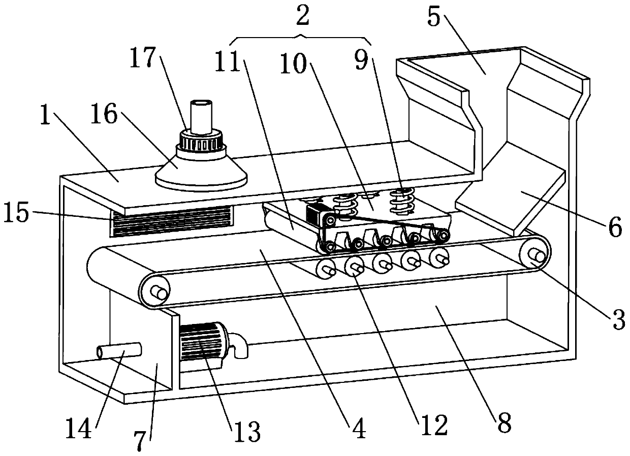
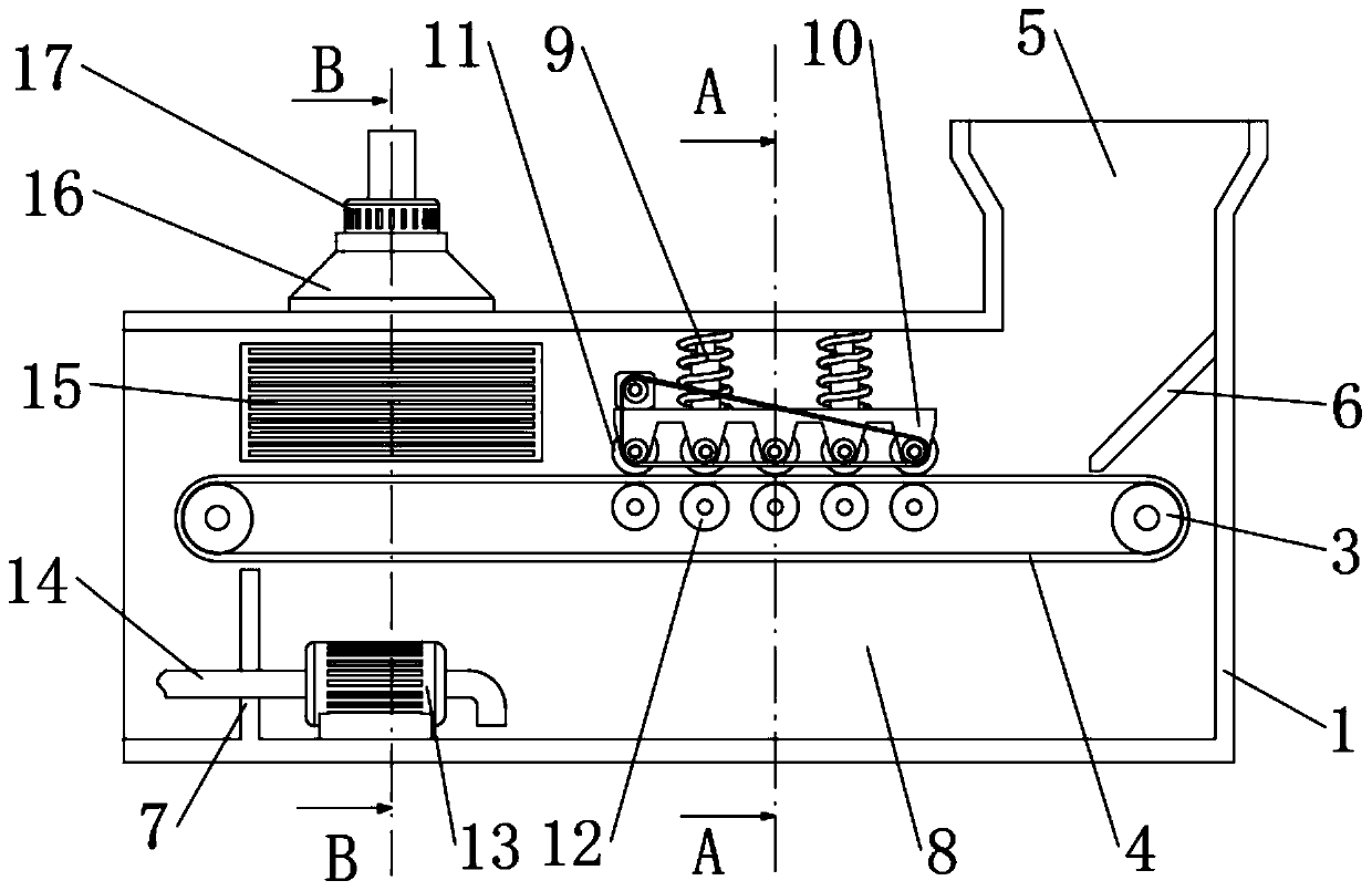
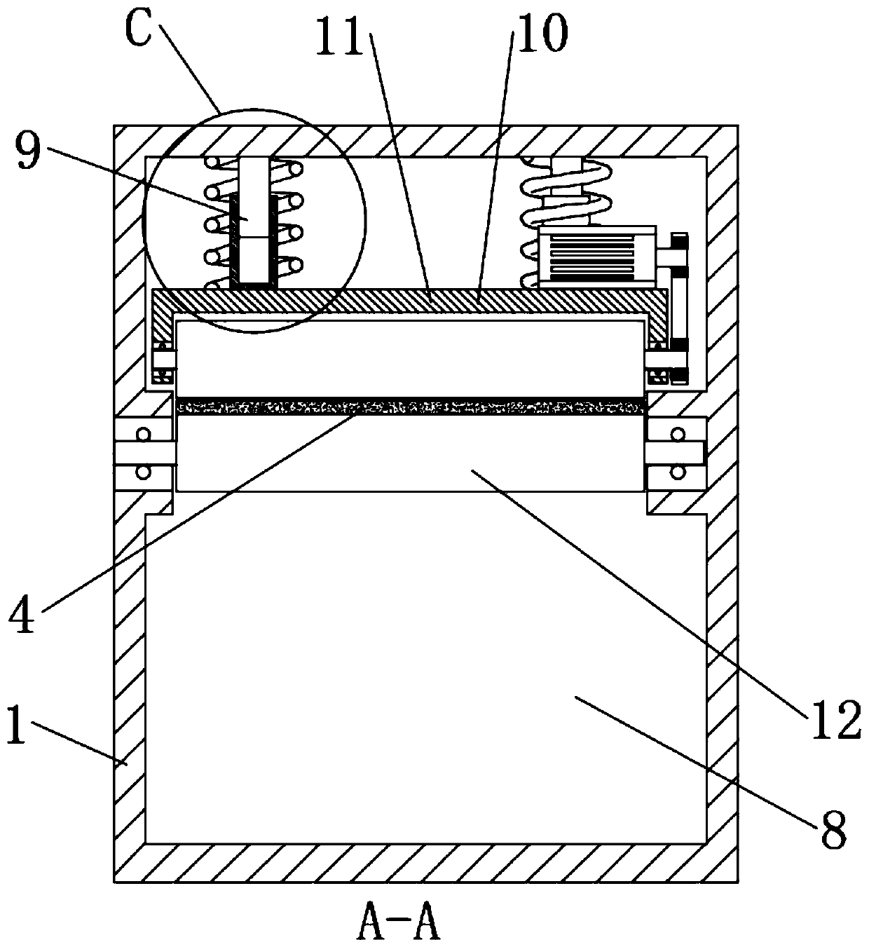
[0021] The present invention provides such Figure 1-5 The one-piece sludge dewatering equipment shown includes a dewatering body 1. A pair of horizontally symmetrical conveying rollers 3 are arranged inside the dewatering body 1. The conveying rollers 3 are connected to the inner wall of the dewatering body 1 through a rotating shaft. A filter belt 4 is connected between the two conveying rollers 3, and a feed inlet is provided on one side of the upper surfac...


PUM


Abstract

The invention discloses an integrated sludge dewatering device, which relates to the field of sewage treatment devices and comprises a dewatering body, wherein the inside of the dewatering body is connected with a filter belt through a pair of conveying rollers; a pressure roller dewatering device is arranged right above the middle part of the filter belt; the pressure roller dewatering device comprises a compression rod group, a pressure roller bottom plate and a pressure roller; warm air ports are arranged on two sides of the dewatering body far away from one end provided with a hopper; anda warm air blower is arranged close to the outside of the warm air port. In the invention, a plurality of pressure rollers of the pressure roller dewatering device are in tight rolling contact with aplurality of support rollers under the action of a compression rod group, and the plurality of pressure rollers are driven by a driving motor, are transported by a filter belt, and sludge passing between the pressure rollers and the support rollers is squeezed, so that moisture in the pressure rollers is discharged; When the warm air blower works, the sludge transported by the filter belt is driedthrough the warm air port, and the extruded sludge is further dried to improve the drying efficiency.

Description

technical field [0001] The invention relates to the field of sewage treatment devices, in particular to an integrated sludge dewatering device. Background technique [0002] Sewage treatment equipment is mainly used for sewage treatment to separate the liquid phase and solid phase substances in the sewage. After the sewage treatment is completed, the separated clear night and sludge are discharged separately. For sludge rich in mineral elements, it is often necessary to Concentration, but the working efficiency of the sludge discharge device of traditional sewage treatment equipment is low, and it is difficult to cope with the increasing amount of sewage treatment tasks; and the dehydrated sludge still contains some water that cannot be dehydrated mechanically. When the dried sludge is processed and transported, a certain processing fee will be added. [0003] In addition, in the prior art, the efficiency of using the method of compressing and covering mud in a closed space...

Claims


Application Information

Patent Timeline
Patent Type & Authority Applications(China)
IPC IPC(8): C02F11/123C02F11/13B01D33/04B01D33/056B01D33/80B01D33/66
CPCB01D33/042B01D33/056B01D33/66B01D33/801C02F11/123C02F11/13
Inventor 不公告发明人
Owner 太原市润民环保节能有限公司
Why Eureka
Try Eureka