
Intelligent control type tunnel automatic deicing trolley

A technology of intelligent control and deicing vehicles, which is applied in snow surface cleaning, construction, cleaning methods, etc., can solve the problems of non-adjustable pole length, inconvenient use and carrying, and endangering train safety, so as to improve the deicing effect and reduce the High labor intensity and high safety effect

Active Publication Date: 2019-09-06
HEBEI ROAD & BRIDGE GROUP
View PDF24 Cites 7 Cited by
  • Summary
  • Abstract
  • Description
  • Claims
  • Application Information

AI Technical Summary

Problems solved by technology

Long-time manual workers are prone to fatigue, and the length of the pole cannot be adjusted, which is inconvenient to use and carry
[0004] In order to reduce the labor intensity of manual deicing, someone invented a tunnel deicing device. An ice melting mechanism is installed on the top of a telescopic rod to melt the ice with hot water. Due to the large specific heat capacity of water, the value is about 4.2× 10³J / (kg℃), melting ice into ice water requires a lot of heat, which can only be provided by a large-capacity power supply, which is difficult to guarantee at the construction site
[0005] In addition, in the deicing of the tunnels that have already been in operation, it is also necessary to consider the trains that are constantly passing by. If the crushed ice falls on the vehicles, it will cause a huge impact and endanger the safety of the trains. Therefore, this deicing operation must avoid passing vehicles

Method used


Image

  • Intelligent control type tunnel automatic deicing trolley
  • Intelligent control type tunnel automatic deicing trolley
  • Intelligent control type tunnel automatic deicing trolley

Examples


Embodiment Construction

[0023] The present invention will be further described below in conjunction with the examples.

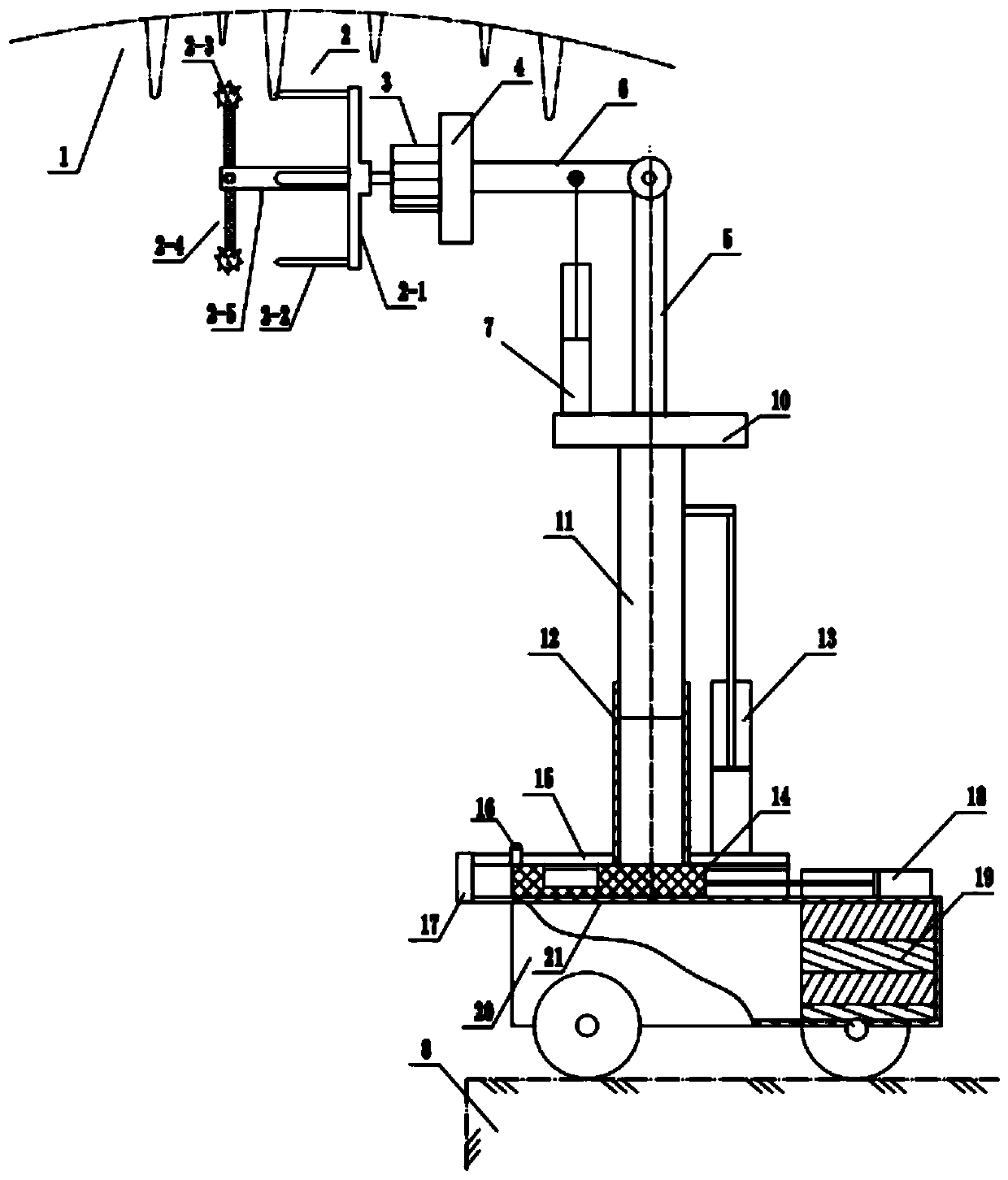
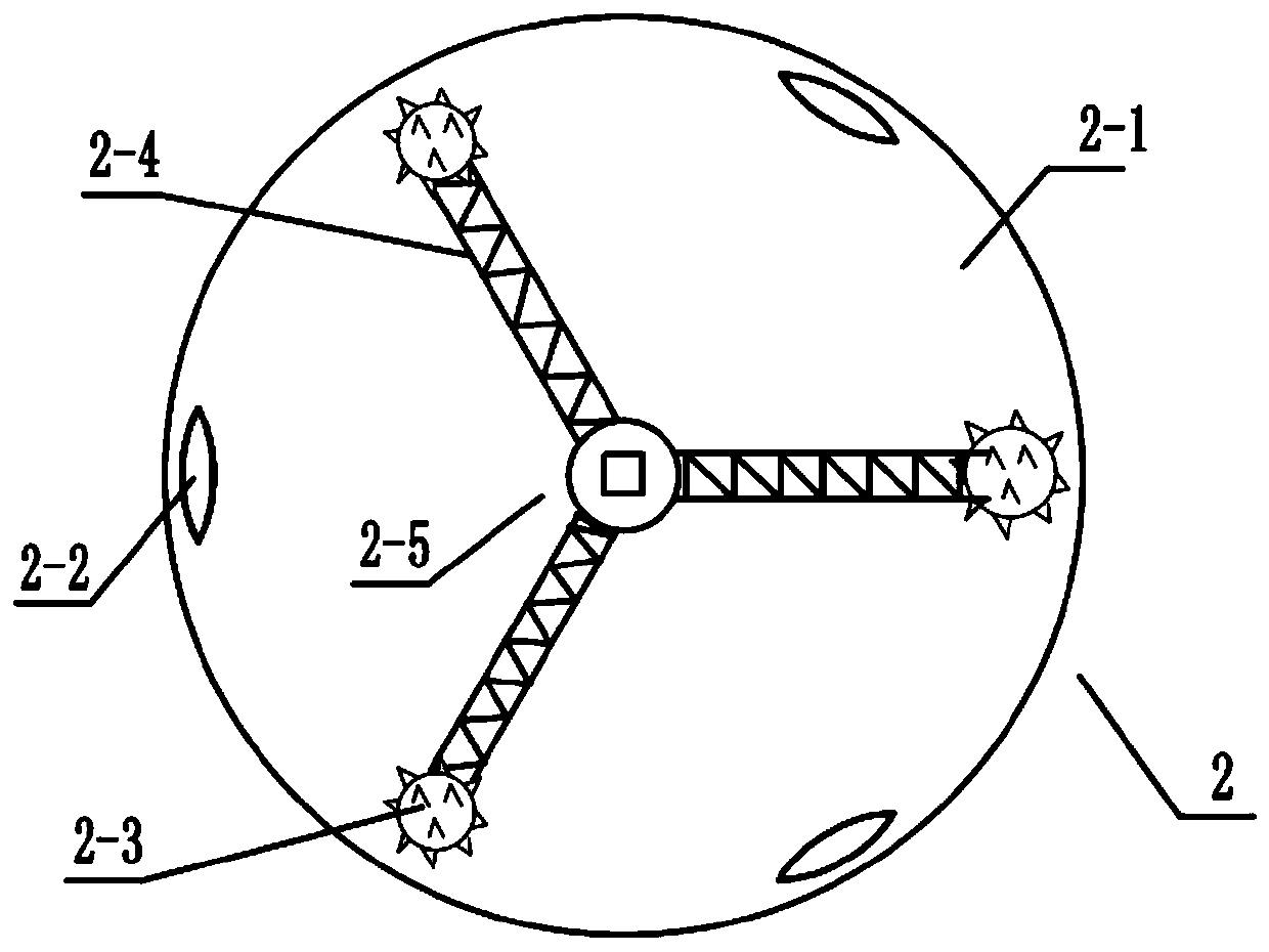
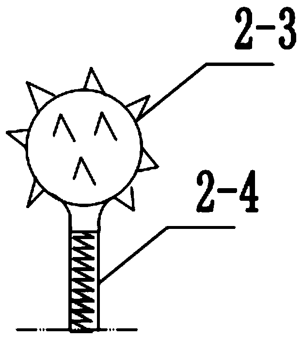
[0024] see figure 1 , The tunnel automatic deicing vehicle of the present invention includes a walking part, a lifting part and a deicing part, the lifting part is fixed on the platform of the walking part, the top seat 10 is fixed on the top of the lifting part, and the deicing part is connected above the top seat. part; the deicing part includes a deicing blade holder 2 and an angle adjustment mechanism, and the deicing blade holder consists of a wheel hub 2-1, a deicing blade 2-2, an ice hammer 2-3, an elastic rod 2-4 and an ice hammer central axis 2- 5 compositions. A plurality of the deicers are arranged, and the intervals are vertically evenly distributed on one side of the hub 2-1. The other side of the hub is provided with a shaft hole, which is connected to the output shaft of the drive motor 3 through the shaft hole; the ice hammer is also provided with The angle adjust...


PUM


Abstract

The invention relates to an intelligent control type tunnel automatic deicing trolley. The intelligent control type tunnel automatic deicing trolley comprises a travelling portion, a lifting portion and a deicing portion, the lifting portion is fixed on a platform of the travelling portion, a top seat is fixed at the top end of the lifting portion, the deicing portion is connected above the top seat, wherein the deicing portion comprises a deicing cutter rest and an angle adjusting mechanism, the deicing cutter rest is composed of an ice cutter seat disc, deicing cutters, an ice hammer, an elastic rod and an ice hammer center shaft, the multiple deicing cutters are provided and are vertically and uniformly distributed on one side of the ice cutter seat disc at intervals, and the ice cutterseat disc is connected with an output shaft of a drive motor. According to the intelligent control type tunnel automatic deicing trolley, an angle-adjusting oil cylinder is also arranged so that theinclination angle of a deicing mechanism can be adjusted, accumulated ice which is difficult to remove can be struck repeatedly, and the deicing effect is improved; and the deicing operation is arranged according to the driving schedule large data, the situation that ice blocks fall to the ground at will, so that trains and personnel are accidentally damaged and hurt is prevented, and the safety is high.

Description

technical field [0001] The invention relates to a cleaning device, in particular to a device capable of deicing in a tunnel. Background technique [0002] As the traffic network increases year by year, the total length of the tunnel also increases sharply year by year. When the weather is cold, the seepage of water in the tunnel is unavoidable and easy to generate icicles, and the icicles hang in the air to form a safety hazard. Due to the high tunnel height and the high speed of trains or cars, when icicles fall, it will also form a large impact force and cause major damage. Tunnel de-icing is an important task that has to be considered in road network maintenance work. [0003] Existing deicing mainly relies on manual deicing. The maintenance worker holds a tunnel deicing rod. A percussion rod and a pulling wire are arranged on the top of the deicing rod, and the percussion rod is controlled by manpower pulling the pulling wire for deicing operation. Long-time manual wor...

Claims


Application Information

Patent Timeline
IPC IPC(8): E01H5/12
CPCE01H5/12
Inventor 刘吉诚王秀玲封艳琴刘学才韩永红李强王祥宇张锐敏李宁王鸿飞
Owner HEBEI ROAD & BRIDGE GROUP
Learn More