
Prestressed light pile for rapidly anchoring emergency bridge inhaul cable and construction method of prestressed light pile

A prestressed, light-weight technology, applied in bridges, sheet pile walls, bridge parts, etc., can solve the problems of increasing the amount of work, prolonging the construction progress, and the weight of steel pipe piles, so as to increase the uplift bearing capacity and improve the uplift resistance. The effect of carrying capacity and reducing transportation costs

Active Publication Date: 2019-09-06
HOHAI UNIV
View PDF6 Cites 2 Cited by
  • Summary
  • Abstract
  • Description
  • Claims
  • Application Information

AI Technical Summary

Problems solved by technology

Traditional anchor piles mostly use driven steel pipe piles, but steel pipe piles have the following limitations: First, steel pipe piles driven into rock formations cause damage to the rock formations around the piles, which affects the play of the pile foundation's uplift bearing capacity. In order to meet the bearing capacity It is often necessary to drive in group piles as anchor piles, which increases the amount of work and prolongs the construction progress; secondly, the steel pipe piles are heavy, and the pile group costs a lot, and the transportation cost for mountainous projects cannot be ignored

Method used


Image

  • Prestressed light pile for rapidly anchoring emergency bridge inhaul cable and construction method of prestressed light pile
  • Prestressed light pile for rapidly anchoring emergency bridge inhaul cable and construction method of prestressed light pile
  • Prestressed light pile for rapidly anchoring emergency bridge inhaul cable and construction method of prestressed light pile

Examples


Embodiment Construction

[0026] Specific embodiments of the present invention will be described in detail below in conjunction with the accompanying drawings.

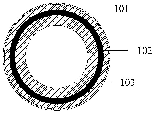
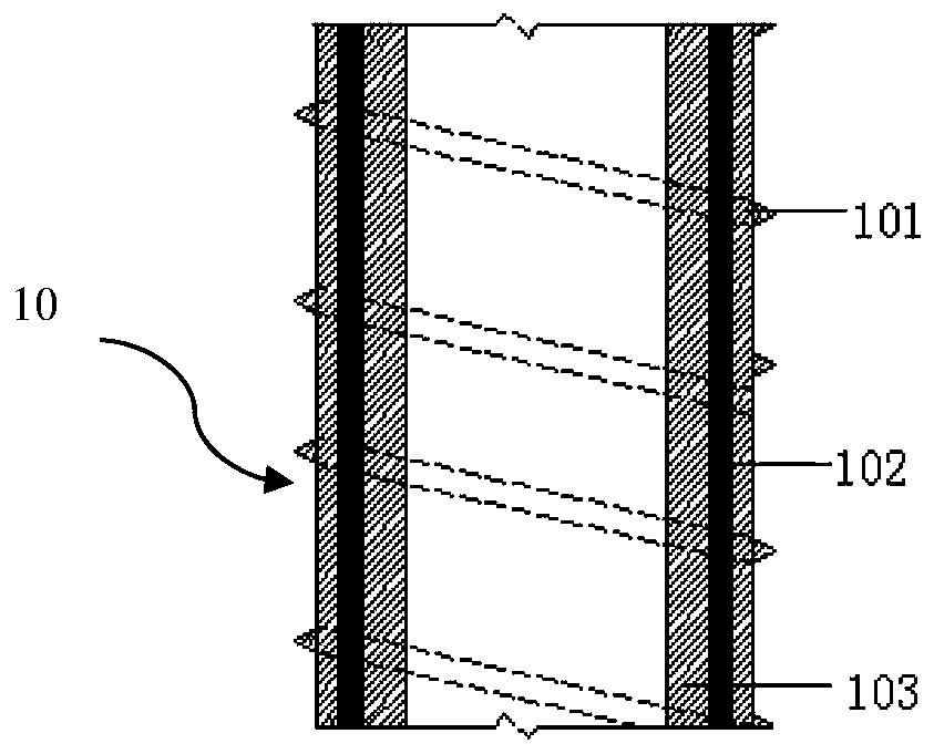
[0027] Such as figure 1 and figure 2 As shown, a prestressed light pile for quickly anchoring emergency bridge cables according to the present invention includes a hollow pile body 10 and a pile cap 20 arranged on the upper end of the pile body 10 and the pile body for interference fit.

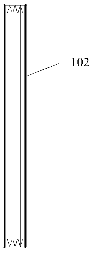
[0028] The pile body 10 is composed of three layers. From the outer layer to the inner layer, it is an outer tube 101, a middle tube 102, and an inner tube 103. The outer tube 101, the middle tube 102, and the inner tube 103 are arranged coaxially. The diameter is equal to the inner diameter of the outer pipe 101, and the outer diameter of the inner pipe 103 is greater than the inner diameter of the middle pipe, so as to realize the interference fit between the inner pipe and the middle pipe.

[0029] The outer tube 101 is a hollow aluminum alloy outer hel...


PUM


Abstract

The invention discloses a prestressed light pile for rapidly anchoring an emergency bridge inhaul cable and a construction method of the prestressed light pile. The light pile comprises a hollow pilebody and a pile cap which is arranged at the upper end of the pile body and is in interference fit with the pile body, and the pile body is composed of an outer pipe, a middle pipe and an inner pipe.The construction method of the light pile comprises the steps that drilling is conducted, the outer pipe provided with a clamp is inserted into the hole, a spiral drilling machine is moved away, an outer spiral pipe clamp is removed, then the middle pipe and the inner pipe are sequentially driven in, after the inner pipe is driven in, the composite middle pipe expands circumferentially, the outerpipe is forced to extrude rock around the pile, circumferential pre-tightening force is generated, the anti-pulling bearing capacity of the anchoring pile is improved, finally, the prefabricated steelpile cap in interference fit is driven into the inner pipe, and the emergency bridge inhaul cable is anchored on the pile cap. The light pile is made of a light aluminum alloy and a composite, and the transport cost is lowered; and through threads on the composite middle pipe and the outer pipe, the anti-pulling bearing capacity of the pile body and pile-soil is improved, the light pile is drivenin on site and used immediately, and the requirements of an emergency bridge are met.

Description

technical field [0001] The invention belongs to the field of geotechnical engineering, in particular to a prestressed light pile and a construction method for quickly anchoring emergency bridge cables. Background technique [0002] China has a vast territory, complex topography, and frequent natural disasters such as earthquakes, mudslides, and landslides. The emergency mobile support capabilities of roads and bridges have become the most critical link in post-disaster rescue and relief. At present, the lightweight, high-strength and modular emergency bridge technology can realize rapid transfer and erection, and the entire installation process has been shortened from the traditional 20 hours to 1-2 hours. Suspension bridges are often used as emergency bridges, and the tension of the suspension cables by anchor piles is required to achieve balanced erection during the erection process. Traditional anchor piles mostly use driven steel pipe piles, but steel pipe piles have th...

Claims


Application Information

Patent Timeline
Patent Type & Authority Applications(China)
IPC IPC(8): E02D5/28E02D5/22E02D5/72E02D7/22E02D7/06E01D19/14
CPCE01D19/14E02D5/223E02D5/285E02D5/72E02D7/06E02D7/22
Inventor 吕亚茹王媛李平
Owner HOHAI UNIV
Learn More