An On-Chip Synchronous Self-Repair System Based on Low Frequency Reference Signal

A reference signal and self-repairing technology, which is applied in the field of radar phased arrays, can solve problems such as synchronization failure, and achieve the effects of strong self-adaptation, low loss, and small area

Active Publication Date: 2020-08-11
烟台芯扬聚阵微电子有限公司
View PDF7 Cites 0 Cited by
  • Summary
  • Abstract
  • Description
  • Claims
  • Application Information

AI Technical Summary

Problems solved by technology

Changes in the environment will lead to failure of synchronization during installation. There is a phase offset between the LO signals of multiple IC chips in the array tile. This static offset is undesirable for phased arrays and needs to be minimized. Achieving synchronization within array tiles
[0003] In addition, the synchronization system needs to make up the delay to an integer multiple of the period. Since the wavelength of the low-frequency signal is too long (for example, the wavelength of the 10MHz reference signal in the air is 30 meters), and the size of the array element tile is usually much smaller than 1 meter, The use of low-frequency synchronous systems requires an equivalent delay line of up to 30 meters, which is unacceptable

Method used


Image

  • An On-Chip Synchronous Self-Repair System Based on Low Frequency Reference Signal
  • An On-Chip Synchronous Self-Repair System Based on Low Frequency Reference Signal
  • An On-Chip Synchronous Self-Repair System Based on Low Frequency Reference Signal

Examples


Embodiment Construction

[0023] The present invention will be described in detail below according to the accompanying drawings and preferred embodiments, and the purpose and effect of the present invention will become clearer. The present invention will be further described in detail below in conjunction with the accompanying drawings and embodiments. It should be understood that the specific embodiments described here are only used to explain the present invention, not to limit the present invention.

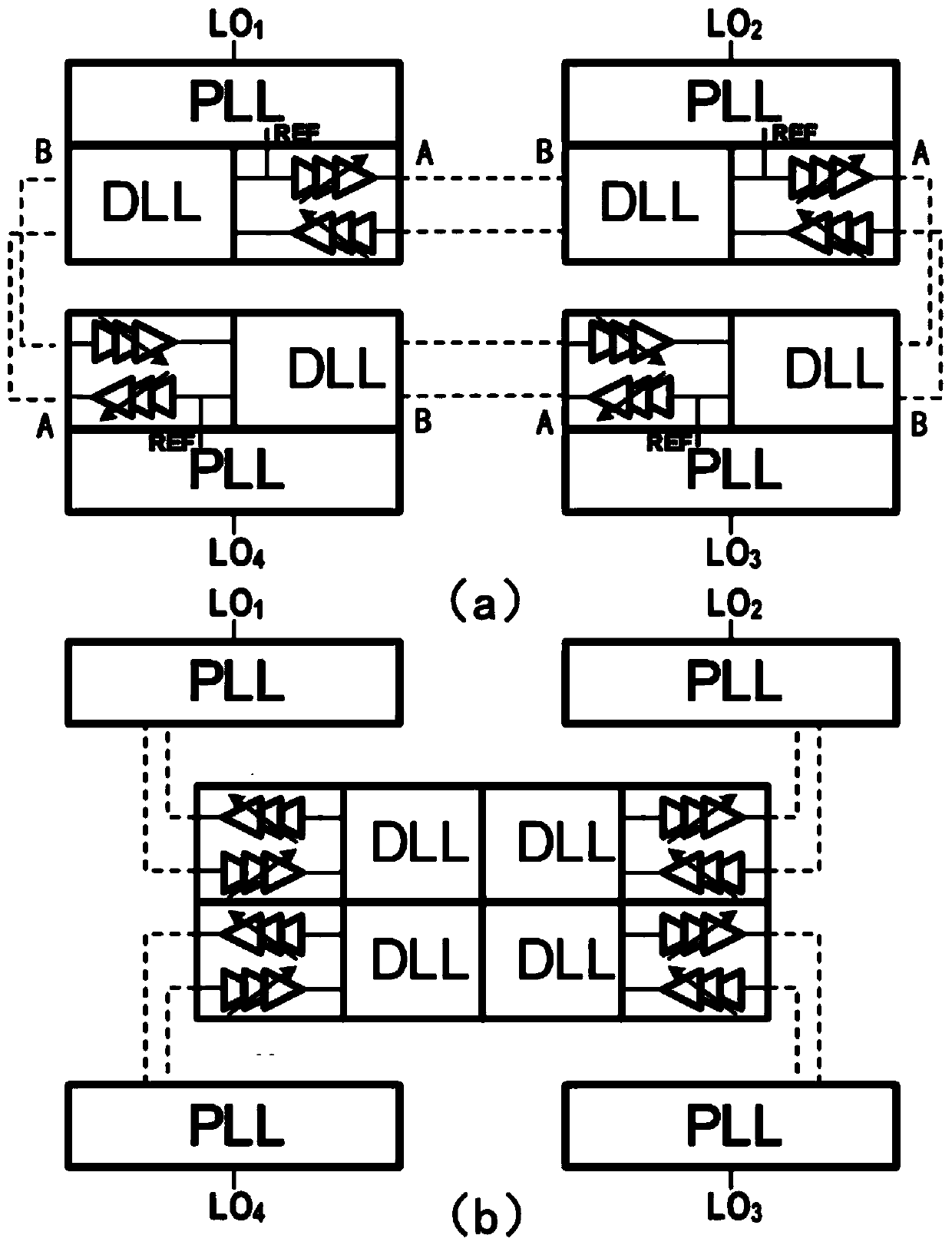
[0024] An on-chip synchronous self-repair system based on a low-frequency reference signal, the system adopts a dual-input PLL star coupling structure or a dual-input PLL butterfly coupling structure, and the PLLs are single-line coupled, and the dual-input PLL star coupling The structure connects n dual-input PLLs through chain closure, and transmits a quarter of the local oscillator signals to each other for interlocking to realize the synchronization of local oscillator signals on-chip; the double-in...


PUM


Abstract

The invention discloses an on-chip synchronous self-repair system based on a low-frequency reference signal. The system adopts a dual-input PLL star coupling structure or a dual-input PLL butterfly coupling structure. Synchronization makes the delay of the whole loop an integer multiple of the reference signal, so as to ensure the synchronization of the local oscillator signals of each IC chip, and uses a transmission line based on an adjustable left-hand material as a delay line to connect to a dual-input PLL to achieve low loss and reduce The physical distance of the delay line is reduced. The system has the advantages of small area, low loss, strong self-adaptation, and strict synchronization in various environments.

Description

technical field [0001] The invention relates to the field of radar phased arrays, in particular to a synchronous self-repairing system for phases of local oscillator signals between digital transceiver chips on array element tiles in the phased array. Background technique [0002] In a large array, how to synchronize each array element is the key technology of phased array. The use of the array requires strict synchronization. For the analog array, the phase difference between the array elements is fixed, and for the digital array, the phases between the array elements are the same; large-scale digital phased arrays are usually composed of multiple array element tiles, and each array element tile contains Several to dozens of digital transceiver chips. There are two types of synchronization requirements in the system: intra-tile synchronization and inter-tile synchronization. Changes in the environment will lead to failure of synchronization during installation. There is a...

Claims


Application Information

Patent Timeline
Patent Type & Authority Patents(China)
IPC IPC(8): G06F15/78G06F15/17H03L7/07H03L7/18
CPCG06F15/7825G06F15/17H03L7/07H03L7/18G06F1/04G06F1/12H04L7/0045H04L7/0331
Inventor 徐志伟王圣杰刘嘉冰邱良弓悦赵锴龙
Owner 烟台芯扬聚阵微电子有限公司
Why Eureka
Try Eureka