Tap changer and temperature rise tester

A tap changer and heat dissipation device technology, applied in the field of electric power, can solve the problems of weak current carrying capacity, poor heat dissipation, low use efficiency, etc., to increase the current carrying capacity, increase the elastic overcurrent contact point, and improve the heat dissipation effect. Effect

Active Publication Date: 2019-09-06
西安西变组件有限公司 +2
View PDF13 Cites 2 Cited by
  • Summary
  • Abstract
  • Description
  • Claims
  • Application Information

AI Technical Summary

Problems solved by technology

[0005] An embodiment of the present invention provides a tap changer to solve the technical problems of low efficiency, weak current carrying capacity, and poor heat dissipation in the prior art of using a knife switch for temperature rise experiments. The method includes: a motor, a transmission shaft , a moving contact assembly, a first static contact assembly, a second static contact assembly and a first controller; wherein, the first controller is used to start the motor; the motor is used to drive the transmission shaft; the first static contact assembly and The second static contact assembly is a strip structure, and includes a plurality of static contacts arranged along the axial direction of the strip; the first static contact assembly is arranged in parallel with the second static contact assembly, and is located in the circumferential direction of the transmission shaft The moving contact assembly corresponds to the first static contact assembly or the second static contact assembly and is arranged circumferentially on the transmission shaft, and is driven by the transmission shaft along with the first static contact assembly and the second Linear reciprocating motion parallel to the central axis of the annular surface of the static contact assembly to realize the disconnection or connection of the first static contact assembly and the second static contact assembly

Method used


Image

  • Tap changer and temperature rise tester
  • Tap changer and temperature rise tester

Examples


Embodiment Construction

[0013] In order to make the purpose, technical solutions and advantages of the embodiments of the present invention more clear, the embodiments of the present invention will be further described in detail below in conjunction with the accompanying drawings. Here, the exemplary embodiments and descriptions of the present invention are used to explain the present invention, but not to limit the present invention.

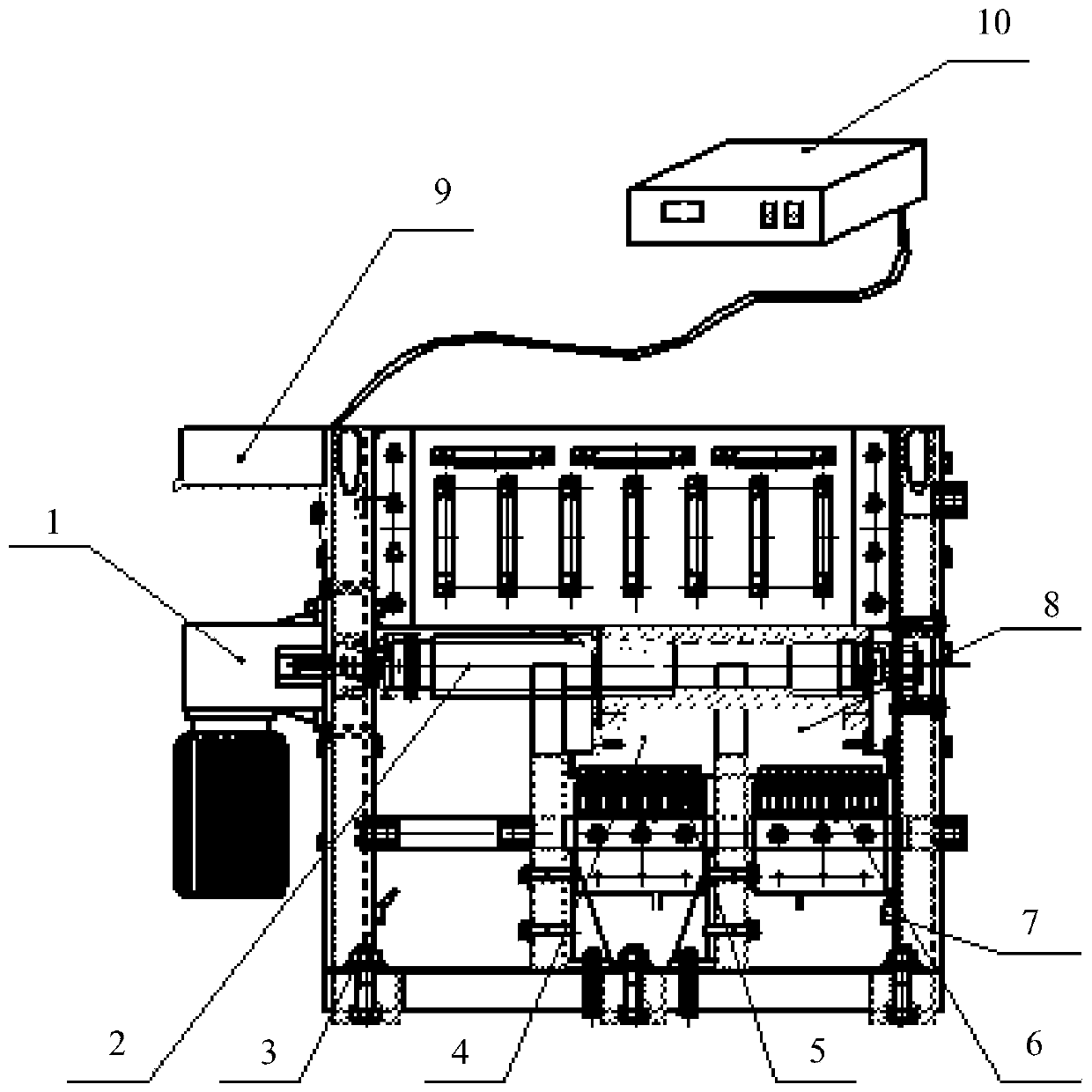
[0014] An embodiment of the present invention provides a tap changer, figure 1 It is a schematic diagram of a tap changer provided in the embodiment of the present invention, such as figure 1 As shown, the tap changer includes: a motor 1, a transmission shaft 2, a moving contact assembly 4, a first static contact assembly 5, a second static contact assembly 6 and a first controller 9;

[0015] Among them, the first controller 9 is used to start the motor 1 to work; the motor 1 is used to drive the transmission shaft 2; the first static contact assembly 5 and the seco...


PUM


Abstract

The present invention discloses a tap changer and a temperature rise tester. The tap changer comprises a motor, a transmission shaft, a moving contact assembly, a first static contact assembly, a second static contact assembly and a first controller. The first controller is used to start the operation of the motor. The motor is used to drive the transmission shaft. Both the first static contact assembly and the second static contact assembly are of strip structures and comprise a plurality of static contacts arranged along the axial direction of the strip. The first static contact assembly and the second static contact assembly are in a parallel arrangement and located in the circumferential direction of the transmission shaft. The moving contact assembly corresponds to the static contactassemblies one by one, is circumferentially arranged on the transmission shaft and moves back and forth along a straight line parallel to the central axis of an annular surface of the static contactassembly driven by the transmission shaft, so disconnection or connection of the first static contact assembly and the second static contact assembly is realized. The tap changer provided by the invention adopts the parallel circumferential arrangement mode of multiple static contacts in groups; the current carrying capacity is greatly increased; the heat dissipation area is increased and the heatdissipation effect is improved.

Description

technical field [0001] The invention relates to the field of electric power, in particular to a tap changer and a temperature rise experiment device. Background technique [0002] This section is intended to provide a background or context to embodiments of the invention that are recited in the claims. The descriptions herein are not admitted to be prior art by inclusion in this section. [0003] Temperature rise is the temperature of each component in electrical and electronic equipment higher than the environment. After the electrical and electronic equipment is powered on, due to the thermal effect of the current, the temperature will continue to rise as time goes by. The part of the temperature rise that exceeds the ambient temperature is called the temperature rise. Temperature rise experiment is one of the important means to test the safety performance of electrical and electronic equipment. [0004] At present, the temperature rise test transformer usually uses a ...

Claims


Application Information

Patent Timeline
Patent Type & Authority Applications(China)
IPC IPC(8): H01H9/00G01R31/00G01K13/00
CPCH01H9/0016H01H9/0027G01R31/00G01K13/00
Inventor 叶传利吕建玉姜鹏翔
Owner 西安西变组件有限公司
Why Eureka
Try Eureka