
System and method for monitoring working states of isolation switches

A technology of isolation switch and working state, applied in the field of isolation switch working state monitoring system, can solve the problems of complicated installation, consuming a lot of manpower and time, and the isolation switch not moving in place, etc., to ensure the accuracy and avoid the effect of observing blind spots.

Pending Publication Date: 2019-09-06
西安图玛智能科技有限公司
View PDF0 Cites 4 Cited by
  • Summary
  • Abstract
  • Description
  • Claims
  • Application Information

AI Technical Summary

Problems solved by technology

This method has big problems in actual use: First, the mechanical device itself has various gaps and wear caused by processing, installation and long-term use, and the rotation angle of the motor and the movement angle of the disconnector cannot be completely synchronized, so There will be a situation where the motor rotates in place but the isolating switch does not move in place, and the judgment error rate is high; secondly, it needs to be confirmed twice by human eyes, which is poor in standardization and requires a lot of manpower and time. With the continuous progress of my country's power grid technology, the intelligent and automatic power grid control technology based on the idea of ​​"one-key sequential control" has entered the substantive implementation stage, and the way of judging by naked eyes is obviously unable to meet the above requirements
However, in the process of judging the state of the isolating switch using video camera measurement, there are still the following problems: video camera measurement uses a digital camera as an image acquisition device, and there is a natural contradiction between its observation range and measurement resolution, that is, the larger the observation range, the lower the measurement accuracy
A substation has dozens or hundreds of isolating switches, and the field of view of a single camera cannot cover all the isolating switches
A separate image acquisition device must be configured for each isolation switch, which has disadvantages such as high cost, complicated installation, and difficult camera control

Method used


Image

  • System and method for monitoring working states of isolation switches
  • System and method for monitoring working states of isolation switches
  • System and method for monitoring working states of isolation switches

Examples


Embodiment 1

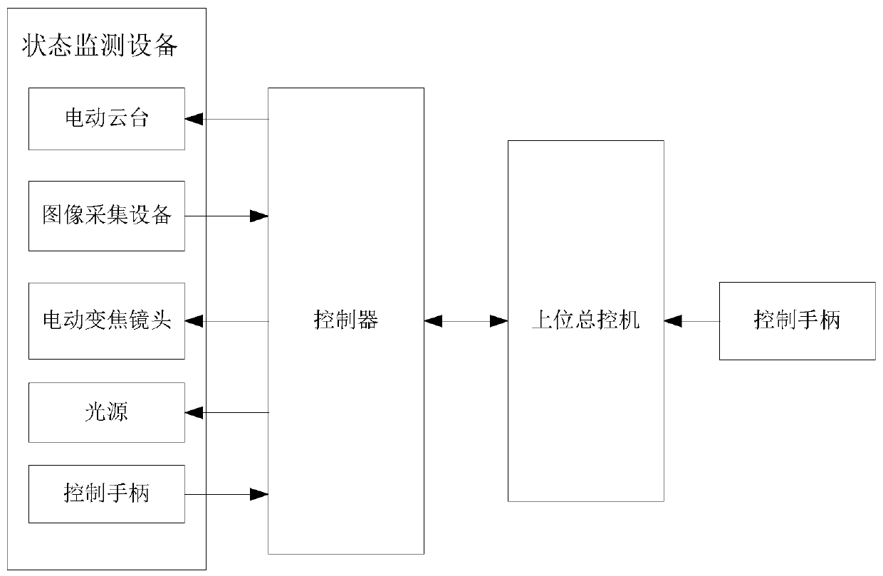
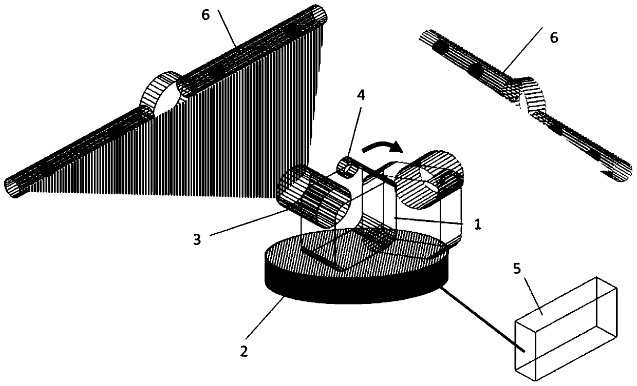
[0057] This embodiment discloses a working state monitoring system of an isolating switch, such as figure 1 with 2 As shown, it includes an upper master control machine, a controller 5 connected to the upper master control machine, and a state monitoring device connected to the controller; the state monitoring device includes an image acquisition device 1, an electric pan / tilt 2, an electric zoom lens 3, and a control handle And light source 4: The image acquisition device is set on the electric pan / tilt, the electric zoom lens is installed on the image acquisition device, the control handle is connected to the controller or the upper master control machine, and the electric pan / tilt, image acquisition equipment, light source and electric zoom lens are respectively connected controller, where:

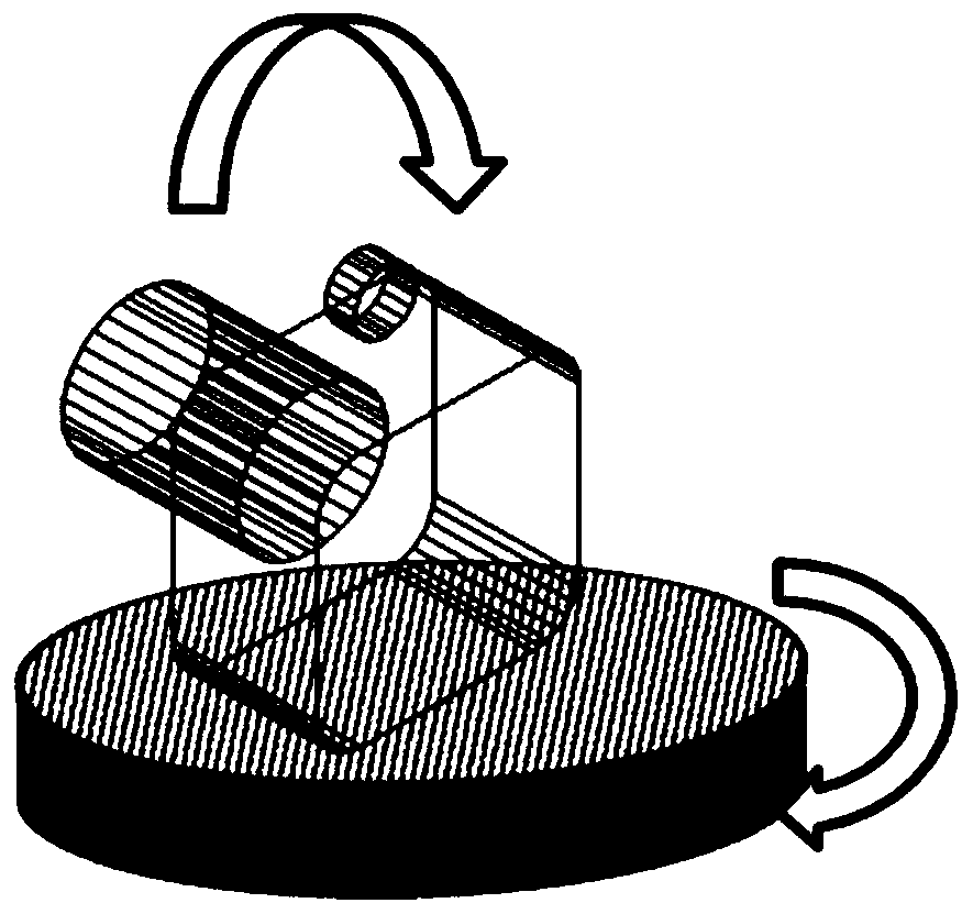
[0058] Electric pan-tilt: used to drive the image acquisition device to rotate; in this embodiment, the electric pan-tilt can be a multi-degree-of-freedom platform, which is provided ...

Embodiment 2

[0070] This embodiment discloses a method for monitoring the working state of an isolating switch based on the system for monitoring the working state of the isolating switch described in Embodiment 1. The steps are as follows:

[0071] Step S1, arrange the position of the electric pan-tilt, and determine the isolating switches that can be photographed by the image acquisition equipment on the electric pan-tilt when it rotates once in the horizontal plane. Wherein, marking points are set on the isolating switch; in this embodiment, such as figure 1 As shown, a plurality of marking points are respectively set on the two arms of the isolating switch which move relative to each other. Specifically, two marking points can be set on each arm of the isolating switch, and the marking points on each arm are sequentially set along the length direction of the arm.

[0072] Step S2. When monitoring the working status of a certain isolating switch, determine the rotation angle of the elec...


PUM


Abstract

The invention discloses a system and a method for monitoring working states of isolation switches. The system comprises a controller and state monitoring equipment; the state monitoring equipment comprises image acquisition equipment, an electric holder and an electric zoom lens; the image acquisition equipment is arranged on the electric holder; the electric holder rotates under the control of the controller; the image acquisition equipment on the electric holder acquires images of the isolation switches with mark points along with the rotation of the electric holder; the electric zoom lens is mounted on the image acquisition equipment and is used for adjusting a shooting focal length of the image acquisition equipment; and the controller controls the electric holder to work, the electriczoom lens to perform zooming and the image acquisition equipment to perform acquisition work, and judges the opening and closing states of the isolation switches according to the positions of the mark points in the current acquired images of the isolation switches. The isolation switches in a large range can be monitored; and the system has the advantages of being low in cost, convenient to mount, simple in image acquisition equipment control, and high in accuracy and automation level of monitoring the working states of the isolation switches.

Description

technical field [0001] The invention belongs to the technical field of electric power detection, and in particular relates to a system and method for monitoring the working state of an isolating switch. Background technique [0002] The isolating switch is the core equipment of the substation. Its function is to ensure the safety of high-voltage electrical appliances and devices during maintenance work, and to isolate the voltage. In the maintenance process of substation equipment, it is necessary to move the isolating switch to the designated position to realize the opening and closing of the circuit. Therefore, whether the isolating switch moves in place directly determines whether the line can operate normally. Considering that the voltage of the substation line can reach hundreds of kilovolts, and the maximum current can reach tens of kiloamperes, if the isolation switch does not move in place, it will cause great damage to the equipment, not only will lead to great econ...

Claims


Application Information

Patent Timeline
IPC IPC(8): H02J13/00
CPCH02J13/0062
Inventor 齐建辉马沁威陆勇王海波
Owner 西安图玛智能科技有限公司
Learn More