Eureka AIR delivers breakthrough ideas for toughest innovation challenges, trusted by R&D personnel around the world.

Fairing clamp

A fairing and fixture technology, which is applied in the direction of manufacturing tools and workpiece clamping devices, can solve the problems of poor versatility and inability to apply fairings of different sizes, etc., and achieves simple structure, stable and reliable clamping process, and strong versatility Effect

Pending Publication Date: 2019-09-10
EULIKIND TIANJIN TECH
View PDF0 Cites 2 Cited by
  • Summary
  • Abstract
  • Description
  • Claims
  • Application Information

AI Technical Summary

Problems solved by technology

[0002] In the prior art, the fairing (also called the hubcap) of the wind turbine is mainly used to protect the hub of the wind turbine. The fairing is generally composed of three one-third fairings spliced ​​together, and the spliced ​​fairings need to be mechanically connected The operation forms a whole. After the mechanical connection, some of the split fairings need to be repainted, and some do not need to be repainted. For the fairings that need to be repainted, in order not to occupy the painting area, the clamp The best position is at the lower edge of the fairing, and for the fairing that does not need to be painted again, in order to improve the clamping stability of the clamp, the clamping position of the clamp is preferably on the side of the fairing. The jigs and fixtures used for fairing assembly and deep processing are generally upper and lower ring hoops, which cannot be applied to fairings of different sizes and have poor versatility. Moreover, the existing fixtures cannot realize different split rectifications according to actual conditions. The clamping effect of different strengths of the cover, the present invention is an improvement on the basis of the above-mentioned technical problems

Method used


Image

  • Fairing clamp
  • Fairing clamp
  • Fairing clamp

Examples


Embodiment Construction

[0025] It should be noted that, in the case of no conflict, the embodiments of the present invention and the features in the embodiments can be combined with each other.

[0026] In describing the present invention, it should be understood that the terms "center", "longitudinal", "transverse", "upper", "lower", "front", "rear", "left", "right", " The orientations or positional relationships indicated by "vertical", "horizontal", "top", "bottom", "inner" and "outer" are based on the orientations or positional relationships shown in the drawings, and are only for the convenience of describing the present invention and Simplified descriptions, rather than indicating or implying that the device or element referred to must have a particular orientation, be constructed and operate in a particular orientation, and thus should not be construed as limiting the invention. In addition, the terms "first", "second", etc. are used for descriptive purposes only, and should not be understood ...


PUM


Abstract

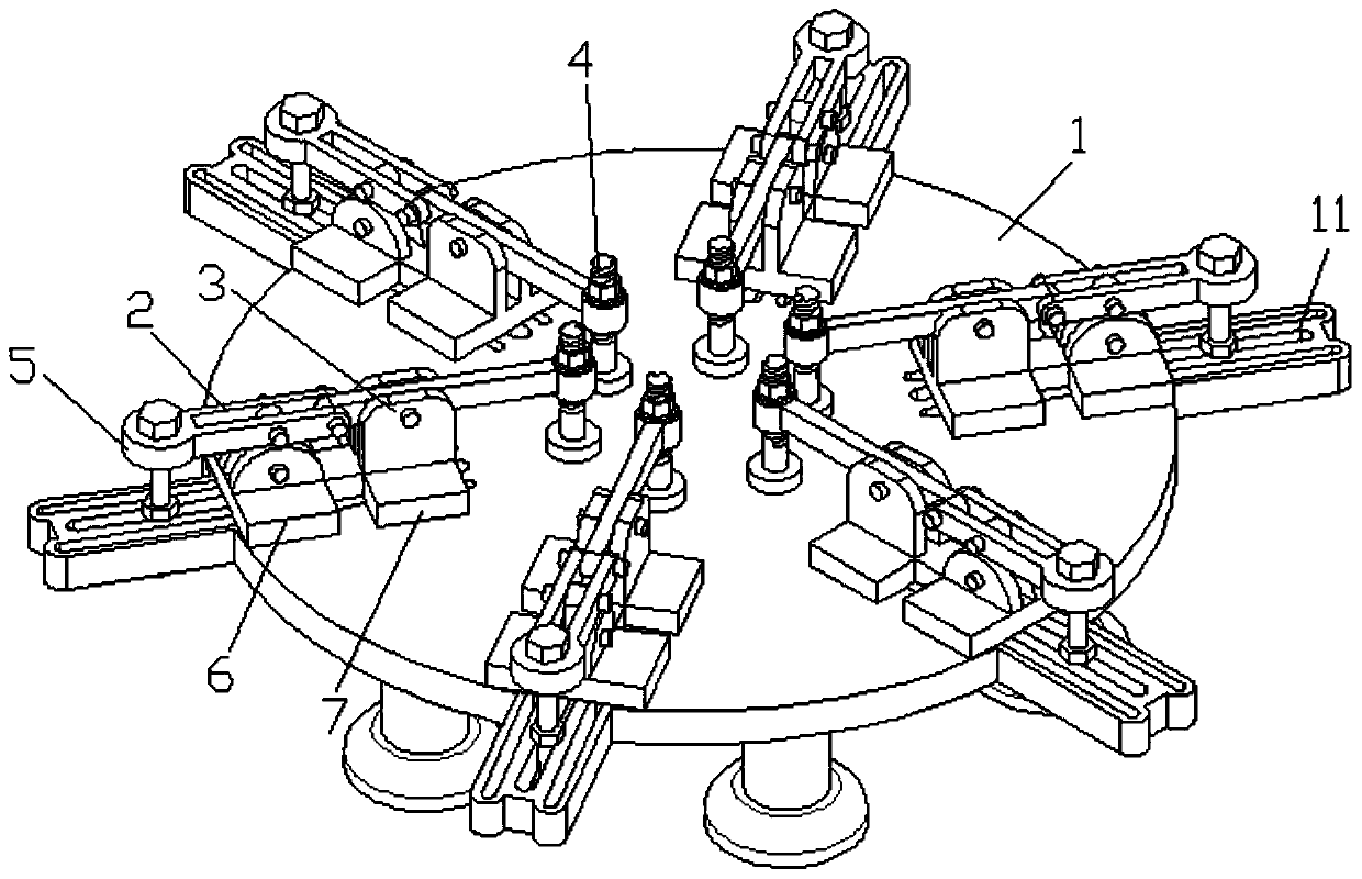
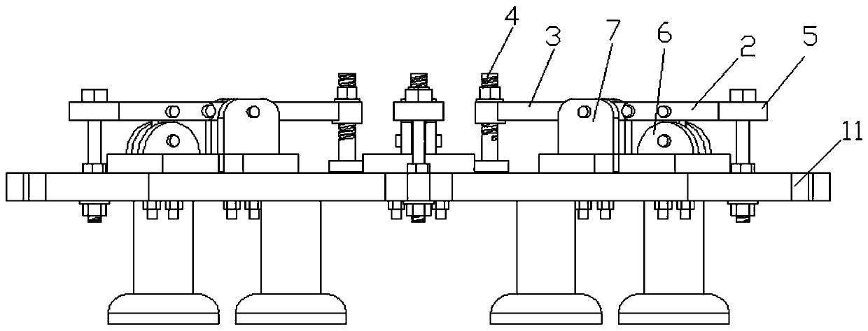
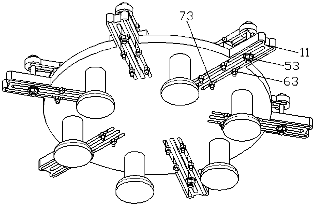
The invention provides a fairing clamp. The clamp comprises a base plate and a plurality of clamping units uniformly distributed on the base plate, each clamping unit comprises a clamping part which is driven by a connecting rod assembly to move and locate; a sleeve part is arranged at the free end of the connecting rod assembly, and inner threads are arranged on the sleeve part; and the clampingpart comprises a clamping bolt and a pressing block which are arranged up and down and fixed by welding, the clamping bolt is in threaded fit with the sleeve part and is fixed by fastening a nut, andthe pressing block abuts against the lower edge of the fairing. The clamp is provided with the plurality of clamping units, the plurality of clamping units are matched to realize the clamping and fixation of the lower edge of the fairing, the plurality of clamping units are independent to one another and have a same structure, each clamping unit can realize the clamping with different or identicalstrength of the lower edge of the fairing through the cooperation of the connecting rod assembly and the clamping part, the clamping units can be applied to clamping fairings with different specifications and sizes, and the universality is high.

Description

technical field [0001] The invention belongs to the technical field of fairing processing tooling, and in particular relates to a fairing clamp. Background technique [0002] In the prior art, the fairing (also called the hubcap) of the wind turbine is mainly used to protect the hub of the wind turbine. The fairing is generally composed of three one-third fairings spliced ​​together, and the spliced ​​fairings need to be mechanically connected The operation forms a whole. After the mechanical connection, some of the split fairings need to be repainted, and some do not need to be repainted. For the fairings that need to be repainted, in order not to occupy the painting area, the clamp The best position is at the lower edge of the fairing, and for the fairing that does not need to be painted again, in order to improve the clamping stability of the clamp, the clamping position of the clamp is preferably on the side of the fairing. The jigs and fixtures used for fairing assembl...

Claims


Application Information

Patent Timeline
IPC IPC(8): B25B11/00
CPCB25B11/00Y02E10/72
Inventor 盖秀春
Owner EULIKIND TIANJIN TECH
Why Eureka
Eureka Blog
Learn More